Axe401 LCD Shield

BillyGreen1973

Senior Member
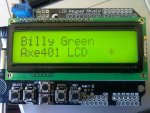
Here is my latest code for running the Arduino/Freeduino LCD Keypad Shield on the axe401 shield base.

A couple of alterations have been made, firstly the pin names have been changed to (protect the innocent ;)) match the shield base numbering system S.0, S.1 etc.

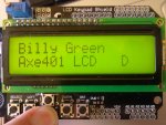
Secondly I've added a fairly crude check of the analog resistor/switch network. The 'Select' switch toggles the backlight, and the others display a letter, in place of the asterisk, to indicate the switch pushed. e.g. 'U' for up etc.
See photos of this running in the next post.
 

Attachments

BillyGreen1973

Senior Member
Photos of this code running.

First photo shows no buttons being pressed, second photo shows the DOWN button being pressed. When the button is released the display reverts to the first photo.

Thanks
 

Attachments

centrex

Senior Member
Not quite the same topic but AXE401.

I have just put the kit together powered it up without the 28x2 to check the voltages are correct.
The power led lights up ok but the led connected to S.13 glows but not at full bright odd I would have thought it should not light at all.

All ok with 28x2 in place and checks ok with flashing test.

Anyone else found this.
Centrex
 
Last edited:

hippy

Ex-Staff (retired)
The S.13 LED is solely to/from the PICAXE/Shield pin so shouldn't glow if there's no 28X2 installed and nothing connected to S.13. Check you don't have a solder short somewhere.
 

BillyGreen1973

Senior Member
Hippy,

if the 4k7 pullup resistors for the onboard I2C socket are fitted, the led will glow dimmly even without the 28x2 being installed. S.13 is also an I2C line and the 4k7 pullup allows a small voltage to flow through the led to ground
 

BillyGreen1973

Senior Member
Centrex, glad you know whats happening now.
Dont forget, if you want to use the I2C EEPROM socket, you DO need to remove the H4 jumper, otherwise the I2C will not work correctly.
 

hippy

Ex-Staff (retired)
Thans for the clarification BillyGreen1973; I overlooked that on the circuit. I've added it to my notes on removing H4 for I2C operation.
 

centrex

Senior Member
Just though I would post my home brew version of the 2x16 lcd shield.
I have not fitted any push buttons yet, you can see all the holes where they are to go under the lcd.
The lcd is driver by a Prof Anderson serial chip under the lcd, this chip only use one io line. The pcb is only single sided so I will have a few jumpers on the board.
28X2 shield.jpg
 
Top