AXE133 to DS1307 Connection

DDJ2011

Member
I have an AXE133 LCD display (which isn;t working but I will follow the hints here to see if I can make it go) . I do however have another question that hopefully someone can help me with:

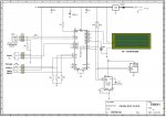
I want to connect my lcd to a DS1307 clock (I didn't buy the AXE LCD with attached clock) and was wondering what might be the best way to do this.

Can anyone help?

DDJ
 

nick12ab

Senior Member
You will need to do some bit banging as portB (the port on which the i2c pins are) is dedicated to driving the LCD.

You'll have to summon the great searching powers of Eclectic as I can't find any bit bang routines.
 

DDJ2011

Member
@nick - Bit banging is mentioned a lot - what does it mean?

Also, I was asking about physical connections too. I could put the DS1307 on its own board but what's the best way to put the whole kit and kaboodle into a bos without breaking anything?
 

Bill.b

Senior Member
Hi DDJ

the AXE133 requires a serial connection while then DS1307 is I2C
they can be addressed by most M2 chips without bit bashing.

here is a schematic of a clock using a 20X2, AX133 and a DS1307.
the code can be addapted for you requirements.

the Display is an OLED 20*4 but can be addapted for the 16 * 2 OLED or LCD.
the control codes are the same for all of the above displays.

Clockcircuit2.jpgView attachment SerialCLOCKamalma.bas

regards Bill
 

westaust55

Moderator
@bill,
In post 1 the comment was:
"I want to connect my LCD to a DS1307"

In other words to emulate at least in part an AXE033.

While the 18M2 has i2c capabilities the necessary pins have ready been aocTed to the LCD interface.
Accordingly, it is necessary to use bit-banged i2c or rework the AXE133 PCB tracks to free up the pins used for inbuilt i2c.
 

hippy

Ex-Staff (retired)
If it is the intent to make an AXE133 work as if it were an AXE033 with Clock add-on, the easiest option would be to use two of the C.0, C.1 and C.2 pins and bit-bang I2C as suggested and alter the rest of the AXE133 driver code as appropriate if needed.

The question is; is the intent to build a standalone module which displays the time using the AXE133 board as its basis, or are we trying to completely emulate an AXE033 using AXE133 + DS1307 ?

The first is likely to be much easier.

Or are we trying to do something else ?
 

DDJ2011

Member
@hippy
The aim is to make a digital alarm clock (see here).

I have a breadboard clock working 18M2/DS1307 and now want to use my LCD screen to display the time (and whatever else).

However, I bought the lcd without clock and so my question really is this:

I understand that I need to create a little board of my own to hold the DS1307 chip but what's the best way to connect this little board to the LCD 18M2 board so that I can get the clock working?

I'm not asking about the wiring to get a working clock (I have that already on my breadboard) I'm asking about the real world physical connections.

As a last resort I will buy an LCD with DS1307, but I would rather make use of what I already have.
 

hippy

Ex-Staff (retired)
I have a breadboard clock working 18M2/DS1307 and now want to use my LCD screen to display the time (and whatever else) ...

I understand that I need to create a little board of my own to hold the DS1307 chip but what's the best way to connect this little board to the LCD 18M2 board so that I can get the clock working?
I'm still confused by what you actually have by the way of hardware and "LCD 18M2 board" is somewhat ambiguous. If you've got the 18M2/DS1307 working and want to add an LCD I don't really see how that entails building a board for the DS1307.

Perhaps draw a block diagram of what you have and want to do or post a circuit diagram.
 

DDJ2011

Member
Clarification

So, I clearly haven't explained well enough what my question is. It does not relate to the circuit diagram. It is about what is the best way to connect two physically separate boards.

I will have two boards for this project. The first is a RevEd AXE133Y Serial OLED Module (16x2) that I have assembled myself. It isn't working but I have another thread to follow to get this working. This board will have the power connected to it.

My second board will just hold a DS1307 clock module (plus crystal and capacitor). This board will be made from stripboard.

So, what I need to learn is how best to connect two boards together physically, ensuring that power flows between the two as well as I2C, serial etc.

Perhaps this is a good start? Pins on each board but then what kind of cable can I use to connect the pins on each board together.

Plus, if I want the boards to sit at 90 degrees to each other, how to I make each one stable? Is there a connector that will turn corners and still allow me to make the electrical connections, or do I need to join the boards somehow (how????) and do the electrics separately?

Many thanks,

DDJ
 

Attachments

nick12ab

Senior Member
I will have two boards for this project. The first is a RevEd AXE133Y Serial OLED Module (16x2) that I have assembled myself. It isn't working but I have another thread to follow to get this working. This board will have the power connected to it.
I'd suggest that you get your AXE133 working before you try to add to it.

DDJ2011 said:
So, what I need to learn is how best to connect two boards together physically, ensuring that power flows between the two as well as I2C, serial etc.

Perhaps this is a good start? Pins on each board but then what kind of cable can I use to connect the pins on each board together.

Plus, if I want the boards to sit at 90 degrees to each other, how to I make each one stable? Is there a connector that will turn corners and still allow me to make the electrical connections, or do I need to join the boards somehow (how????) and do the electrics separately?
Techsupplies have sockets for these connectors - see here (CON043, CON044, CON045, CON060, CON061) - and also offer the headers you have linked at a lower price (CON037).
 

Captain Haddock

Senior Member
If you look for 'learning to drive an lcd' thread in the code snippets forum there is some excellent codes from Marks that will do away with the need for a serial driver and still free up the i2c pins of a 20x2, I have it running at the moment with 2 inputs controlling 4 relays while reading temp from 5 ds18b20's and reading from ds1307, display(20x4 lcd) shows day/month/date/hours/mins/secs/5x temps and updates very fast.
Theres something satisfying about taking an extra 18 pin chip out of a circuit
 

hippy

Ex-Staff (retired)
Thanks for the clarifications DDJ2011.

You can take the AXE133Y board and use the 5-pin connection on the AXE133Y board to go to your DS1307 breadboad; 0V, +V, C.0, C.1, C.2

Because the lines for hardware I2C are used for driving the LCD you will have to bit-bang I2C via two of the C.0, C.1 and C.2 pins.

Once you have the bit-banged I2C code working your AXE133Y 18M2 will be able to read and write data in the DS1307 by calling the appropriate subroutines.
 
Top