AXE091 Dev Board arrived yesterday arvo

rigidigital

Senior Member
Might help to click on thumbnail jpg to understand my post!


I received late yesterday all the Picaxe parts I'd ordered. A great moment as I hadn't put my hands on a chip for 3 to 4 years. I am starting allover again!

First I soldered up a breadboard adapter ,realised when it was nearly done I had used the wrong side on a couple of components so its rubbish. No worries , not needed really to put a stereo connector on a board.

Today I took out the AXE091 development board. No instruction at all. There will lots of trial and even more error :)

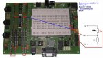
I had small trouble getting pin 5 High to light a LED on the AXE091 Dev Board.
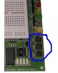
The pin sockets circled in red are numbered 1 through 10. While 08M was running
I tried to use both pin socket 5 then 2. Neither got the LED working.

On the Right side of socket holding the 08M the pin sockets number 11 to 20.
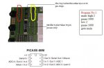
The pin socket that went high was number 18 which is directly adjacent to the 5th
Pin of the 08MPicaxe. And that pin is called/referred 2 when programming.

So I just found the numbering of pin sockets useless when all that happens is the pin socket is ‘bound’ to the adjacent pin of the Picaxe right beside it.
 

Attachments

rigidigital

Senior Member
I willnow!

Well I am ashamedly guilty of not looking or even thinking of the data sheet. Thank you, I was planning on spending half the night at least to find out relatively simple thing. There is hope yet, thanks again.
EDIT:
I had read that PDF but thus far I don't think I have got much out of it at all. It also has lots of diagrams on how different picaxe are wired and connected. I think that's good if you are putting them on a breadboard from scratch but I don't know why is on the AXE091 PDF data sheet?

Right now I'm trying to see how to use the three switches, Ill go over the datasheet again and trytosee
 
Last edited:

rigidigital

Senior Member
Not sure how to get switches working

So there are three switches SW1,SW2,SW3, and the blurb below from the data sheet.
---------------------->

"""Digital Input Switches (SW1, SW2, SW3)
Three switches are provided. The input is tied low by a 10k resistor, with the switch
connected between the input and V+. Therefore pressing the switch will result in a
high signal.
Commands - if pin... then""<<<---------------------------

I'm at a loss how to use them but working on it.
 

Attachments

hippy

Ex-Staff (retired)
The three switches go to socket pins labelled "SW1", "SW2" and "SW3" ( to the left of the LDR ), take a wire from whichever you wish to use to the socket pin for the PICAXE input you will be using. When the switch is pushed the PICAXE input wil go high, when not pushed the input will be low.
 

rigidigital

Senior Member
Thanks Hippy, I to be honest wasnt even sure whataheader was. I put my glases on(first year I have ever needed them, so i usully won't wear them) then I saw plain as day the pin sockets for each switch in/on header. Ill still folow ur advise thankyou.
 

hippy

Ex-Staff (retired)
Thanks for that, but one error ... for the 18-pin, the adjacent socket strips are 10 pin per side, the lower two pins are 0V on the left +V on the right, leg 9 and leg 10 are the next ones up.

On my board I unsoldered the 100nF above and below the 18-pin and put them underneath the board; that allows 18-pin PICAXE's to be removed more easily if you haven't got a chip puller.
 
Last edited:

UmBongo

Member
Is it possible to fit ZIF sockets in to the DIL sockets that receive the PICAXES? I thought to ask in case anyone had any experience or advice on this idea.

As I seriously bent the legs on my 08M when inserting. Removal looks to be difficult without a dedicated removal tool.
 

westaust55

Moderator
I do not think you will have enough room for a ZIF type socket.

While the two pins are at the usual spacing (eg 0.3 inch), from my experience the ZIF socket will overhang at least 4 holes (0.4 inch) at the lever/pin1 end and by at least 2 holes (0.2 inch) at the other end. Also for a 0.3 in wide chip the ZIF socket will be about double the width of the actual chip.

So in summary ZIF socket width may be okay but think insufficient room length wise
 
Last edited:

hippy

Ex-Staff (retired)
Is it possible to fit ZIF sockets in to the DIL sockets that receive the PICAXES? I thought to ask in case anyone had any experience or advice on this idea. As I seriously bent the legs on my 08M when inserting.
Probably not for the size issues westaust55 describes but you might get lucky. You could perhaps insert a ZIF into the actual DIL sockets as and when required.

The main way to avoid bending legs on insertion is to use a leg straightener so the legs are bent straight downwards and slot straight into the socket holes rather than being splayed out as they are usually delivered. It is possible to place the IC sidewards on a flat surface then tilt the IC so the legs straighten that way but takes a bit of practice to get right and easier with larger chips -

http://www.ladyada.net/images/mshield/bendchip.jpg

Removal looks to be difficult without a dedicated removal tool.
Removal with an IC-puller is the best way but it can be achieved by carefully sliding a thin flat-end screwdriver between the socket and chip. You want to slide it so as it goes in it lefts the IC rather than tilt it out which will twist the legs. Don't forget to turn power off first no matter what's used.

Worst way to remove an IC is to grab its ends between finger and thumb and pull. It invariable rotates as it comes free, puts a neat line of holes in finger or thumb which are very painful and bends the pins. Though it's equally a badge of honour / rite of passage along with the blister from touching a soldering iron tip to see if it's hot :)
 
Last edited:

Dippy

Moderator
Most Dev boards exhibit and cause similar pain.

What I (and others here) do is put the PICAXE into an IC socket and plug the whole thing into the Dev board socket.
Then use the screwdriver technique to get the whole thing out.
Still not as good as ZIF but at least you only bend legs on a cheap ic socket rather than your PICAXE.

The other option is to make a ZIF adaptor or daughter-board.
A one-off pain , but, therafter, a luxury.

It has to be said that some ic sockets have not been designed by someone without a brain and the chip fits so snugly that stuffing in a screwdriver or one of those cheapo ic removers is awkward.

Dunno about your Rev Ed board but all my MikroE dev boards are really awkward in that respect and I have punctured my fingers on many occasions - exactly as described by hippy :)

Leg straighteners are highly recommended - you can get cheap/good ones for 0.3 and 0.6" all over the place now.
Not sure if Rev-Ed sell them but I think Rapid sell them for under a fiver.

If your chip really gets stuck I can also recommend Just For Men and Regain.
 

SAborn

Senior Member
Im glade you guys have called the tool a "leg straightener" and not a "leg opener" as some have.

It do cause some problems when the wrong name is used, as the second is often a stiff drink puchased for a ........well lets just say someone else.

Although you might well need the stiff drink once you get bitten on the finger by a angry IC when removing it from a socket...it really do hurt as the pins go in and bend inside your finger like a staple, and removing it from the finger is even more painfull.
 

kollinsb

Member
I recently bought a AXE091 and it's nice! Definately recommended!

Is there a way to use the 3V chips (like the 20X2) on the board outside of removing a chip out of the applicable "slot" and using the breadboard?
 

hippy

Ex-Staff (retired)
There is. Disconnect any PSU you have going to the board's power inlet socket then supply power to the screw terminals next to that socket. This will operate the entire board at whatever voltage you put in. This is how I run my AXE091 with a bench suppy into the screw terminals.

Take care to get the 0V and 3V connections round the correct way as there's no reverse voltage protection when operated this way, nor any over-voltage protection.

If you need to mix 3V and 5V parts you will have to use the breadboard area or separate boards.
 

rigidigital

Senior Member
i like the idea of a lrg straightner. i had one 08M withlots of crushed legs .Took a while but with a fine pair of plyers and frequent trips to the soket but i got it into the AXE091 and working.
 

hippy

Ex-Staff (retired)
ZIF sockets can be handy for straightening legs up, just drop the chip in and let the clamps close slowly. More serious bending may need less subtle persuassion :)

If you do snap the lower part of the leg off it's not the end of the world if there's still the top part which goes into the chip. Get a DIL socket, jam a wire into the socket where the pin snapped off. A blob of solder to keep it in the socket ( it may well melt part of the DIL socket but hey ), insert the chip, solder the broken pin to the wire. It's a quick fix while waiting for a new chip to turn up.
 

UmBongo

Member
There is. Disconnect any PSU you have going to the board's power inlet socket then supply power to the screw terminals next to that socket. This will operate the entire board at whatever voltage you put in. This is how I run my AXE091 with a bench suppy into the screw terminals.

Take care to get the 0V and 3V connections round the correct way as there's no reverse voltage protection when operated this way, nor any over-voltage protection.

If you need to mix 3V and 5V parts you will have to use the breadboard area or separate boards.

I don't quite understand your advice, but it might be linked to my experiences today as I tried to use a 20X2 (PIC18F14K22) and I could not get the Programming Editor to recognise the chip.

I am powering the AXE-091 with 3AA@1.5v and I put the programming cable in to the socket near the bottom left hand side of the board. Is this related to the post #17 or the reason I can not get my chip to take a program?
 

hippy

Ex-Staff (retired)
With the power connector to the top, PICAXE sockets to the left, a 20X2 should go in the top PICAXE socket, notch of the chip to the top, AXE027 into the top jack.
 

kollinsb

Member
I am powering the AXE-091 with 3AA@1.5v and I put the programming cable in to the socket near the bottom left hand side of the board. Is this related to the post #17 or the reason I can not get my chip to take a program?
If you are trying to power the 20X2 with 3X 1.5AA that's a bad thing... Should use no more than 3.6V (I believe)...
 

hippy

Ex-Staff (retired)
I think there's some confusion creeping in between PICAXE which can operate at 3V ( and also up to 5V ) and the PICAXE-28X2-3V and 40X2-3V which can operate at up to 3.6V only.

All PICAXE except those two can operate at up to 5.5V.
 

UmBongo

Member
Hippy:

"With the power connector to the top, PICAXE sockets to the left, a 20X2 should go in the top PICAXE socket, notch of the chip to the top, AXE027 into the top jack. "

Thanks for the explanation. I was putting the chip in to the totally wrong socket!! And next to each socket it does have an etched description of the types of chips - which I forgot about! :) And thanks for the reminder about the operating voltages of the different chips.


rigidigital - hope I did not side track on your original thread too much - certainly not intentional!
 
Top