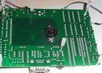
AXE091 board and DS1307
- Thread starter Tony P
- Start date
http://www.techsupplies.co.uk/epages/Store.sf/en_GB/?ObjectPath=/Shops/Store.TechSupplies/Products/BAT004HSM
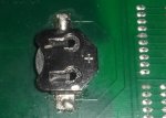
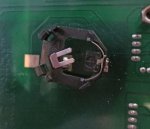
Sorry for the rushed pics.
e
Sorry for the rushed pics.
e
Attachments
-
 183.7 KB Views: 26
 -
 142.8 KB Views: 24
Having hooked up the SDA/SCL connections that are shared between the DS1307 and the EEPROM to the i2c pins on your PICAXE, read the i2c tutorial.How do I use the DS1307 on the project board? There is not much info in the manual (not that I can understand anyway!!)
I have followed all instructions to the letter but if I try to display the time on my AXE033 LCD all I get is 255:255:255 as the timeHaving hooked up the SDA/SCL connections that are shared between the DS1307 and the EEPROM to the i2c pins on your PICAXE, read the i2c tutorial.
I have the the SCL output connected to pin 7 and the SDA output connected to pin 10 of my 18M2
Code:
#PICAXE 18M2
	hi2csetup i2cmaster, %11010000, i2cslow, i2cbyte


MAIN:
	PAUSE 2000
	hi2cin 0,(B0,B1,B2)
	DEBUG
	serout B.7,N2400, (254, 1)
	pause 500
	serout B.7,N2400, (254,128)
	serout B.7,N2400, (#B0,":",#B1,":",#B2)
GOTO MAINWrong way round. SCL is leg 10 and SDA is leg 7.I have the the SCL output connected to pin 7 and the SDA output connected to pin 10 of my 18M2
See the PICAXE-18M2 pinout.
I also realised that I posted the wrong code. Here is the correct one
Code:
#PICAXE 18M2
	 i2cslave %11010000, i2cslow, i2cbyte


MAIN:
	PAUSE 2000
	hi2cin 0,(B0,B1,B2)
	DEBUG
	serout B.7,N2400, (254, 1)
	pause 500
	serout B.7,N2400, (254,128)
	serout B.7,N2400, (#B0,":",#B1,":",#B2)
GOTO MAINwestaust55
Moderator
The reason you are seeing values like 128 is that the values you read in from the DS1307 are in BCD format.
Your will need to use the BCDTOASCII command for the seconds, minutes and hours to generate separate tens and units digits and then send these to the display.
To save on having to use many variables, use the BCDTOASCII with the hours first and send that to the display, then do the minutes and finally the hours.
Try this:
Code:
#PICAXE 18M2
	 i2cslave %11010000, i2cslow, i2cbyte


MAIN:
	PAUSE 2000
	hi2cin 0,(b0,b1,b2)
	DEBUG
	serout B.7,N2400, (254, 1)
	pause 500
	serout B.7,N2400, (254,128)
	b4 = b2 : GOSUB Convert : SEROUT B.7, N2400, (":")
	b4 = b1 : GOSUB Convert : SEROUT B.7, N2400, (":")
	b4 = b0 : GOSUB Convert
		GOTO MAIN

Convert:
	BCDTOASCII b4,b5,b6
	SEROUT B.7, N2400, (b5,b6)
RETURYes it is - from i2c tutorial: "All the time/date data is in BCD (binary-coded-decimal) format"Why are things like this not written in the manuals and the example codes?
To be fair, the i2c tutorial does not contain a good example for displaying the time, and the example here is not very good at all.
Bill.b
Senior Member
This code will display in 12 hour format. This is only part of complete clock program.
Bill
Code:
symbol TempHour 		= b24		'Tempory store - Hours
symbol OLED		= b.7		'Serial output to display
symbol Baud		= N2400	'Set serial output baud rate
symbol seconds 		= b7		'DS1307 seconds
symbol mins 		= b8		'DS1307 minutes
symbol hour 		= b9		'DS1307 Hour
symbol day 		= b10		'DS1307 day
symbol date 		= b11		'DS1307 Date
symbol month 		= b12		'DS1307 Month
symbol year 		= b13		'DS1307 Year
symbol control 		= b14		'DS1307 Control
symbol AsciiData1 	= b17		'Ascii data for display on LCD
symbol AsciiData2 	= b16		'Ascii data for display on LCD
symbol AsciiData3 	= b20		'Ascii data for display on LCD
symbol AsciiData4 	= b19		'Ascii data for display on LCD
symbol AsciiData5 	= b23		'Ascii data for display on LCD
symbol AsciiData6 	= b22		'Ascii data for display on LCD
symbol AsciiData7 	= b25		'Ascii data for display on LCD


	pause 2000
	serout OLED,Baud,(254,1)			'Clear Display

main:
	gosub TimeDate12
	goto main
TimeDate12:

	gosub readtime			'get current time form DS1307
	serout OLED,Baud,(254,128)    'calculate 12 hour display from 24h data
	Temphour = hour
	if hour >9 then
		Temphour = hour - 6
	endif
	if hour >18 then
		 Temphour = hour - 18
	endif
	if hour >25 then
		 Temphour = hour - 24
	endif
	if hour =0 then
		Temphour = 12
	endif
	bintoascii Temphour,AsciiData7,AsciiData2,AsciiData1	'Convert Time  To ASCII for display
	bcdtoascii mins,AsciiData4,AsciiData3
	bcdtoascii seconds,AsciiData6,AsciiData5
	if AsciiData2 = 48 then					'remove leading 0
		serout OLED,Baud,("    ",AsciiData1,":",AsciiData4,AsciiData3,":",AsciiData6,AsciiData5)
	else
		serout OLED,Baud,("    ",AsciiData2,AsciiData1,":",AsciiData4,AsciiData3,":",AsciiData6,AsciiData5)
	endif
				'display am or pm
	if hour > 17 then
		serout OLED,Baud,(" pm    ")
	else
		serout OLED,Baud,(" am    ")
	endif
	serout OLED,Baud,(254,192)
	return


readTime:
	hi2csetup i2cmaster, %11010000, i2cslow, i2cbyte    	' set DS1307 slave address
	hi2cin 0,(seconds,mins,hour,day,date,month,year)  	'Read date and Time
	return
Bill
Hemi345
Senior Member
Because it seems they don't want to give all the answers, just enough information to either push you in the general direction or frustrate the hell out of you. This topic has been asked so many times, you would think they would just put a working example on the website in the Circuit Creator section or even a link to the I2C tutorial in the Commands section of the website or Manual 2. I eventually found the I2C tutorial a few months back in the datasheets section but still looking for the elusive one-wire tutorial.Why are things like this not written in the manuals and the example codes?
westaust55
Moderator
Such information is also given in the DS1307 Datasheet.
It really is worth downloading (readily available - just google) the relevant Datasheet for any new IC/chip that you are going to use.
It really is worth downloading (readily available - just google) the relevant Datasheet for any new IC/chip that you are going to use.