Hi,
I have an AXE049 board and the Picaxe shop link here says it has:
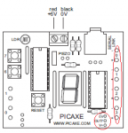
In the attached diagram (ripped from the AXE049 pdf - sorry!) I think I need to connect my AXE133Y to the solder points in the circled area (0v, Out7, V+) rather than one of the 4 pairs of +/- points in the other highlighted area. Is this correct?
Follow up question is how do I address this port? The chip on board is an 18M2 and although the circuit board suggests output 7 (ie it says Out7 on the board itself) I think I need to address it as either pinB.7 or pinC.7
Hopefully this will be a quick one for someone to help with!
Many thanks,
DDJ
I have an AXE049 board and the Picaxe shop link here says it has:
"Solder pads to allow a piezo and servo/serial LCD to be added".
In the attached diagram (ripped from the AXE049 pdf - sorry!) I think I need to connect my AXE133Y to the solder points in the circled area (0v, Out7, V+) rather than one of the 4 pairs of +/- points in the other highlighted area. Is this correct?
Follow up question is how do I address this port? The chip on board is an 18M2 and although the circuit board suggests output 7 (ie it says Out7 on the board itself) I think I need to address it as either pinB.7 or pinC.7
Hopefully this will be a quick one for someone to help with!
Many thanks,
DDJ
Attachments
-
 17.6 KB Views: 17