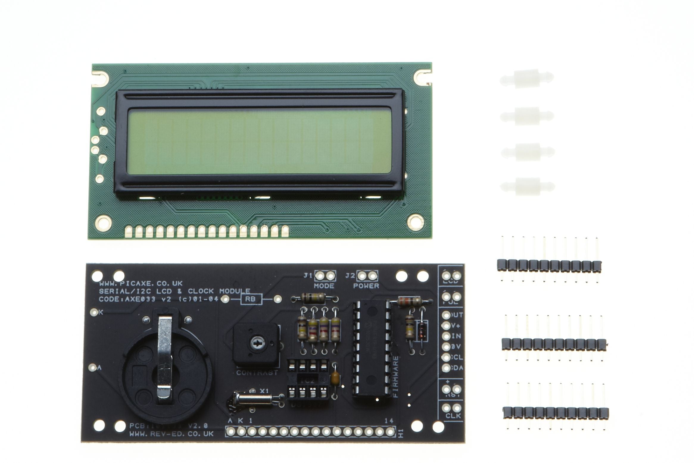
AXE033 OLED Module problem

Phil P

New Member
I have done a silly thing and touched a pad with a piece of metal and the display has stopped working. It has been working for years and the display - yellow on black - is super and I miss it. I fitted an RTC when built the module and that is still working as well as the flashing LED. I am using a I2C interface. Rather than bin the display I was wondering if it repairable. I could try to drive the display independently of the attached board but that is a lot of work. Could I programme a PIC16F819-I/P or buy a new one to see if that was the problem but I don't have the code. The module says v2. Any guesses appreciated.
Phil
 
You could buy the pcb (on sale) and just swap the chip over:

 
The AXE033 seems to be for LCD, although I suspect the interfaces are probably the same.
I think the IC is a Picaxe 18M or 18M2, which you could program/reprogram using the code RevEd provide.
Also, I see that the PCB itself is on sale at £4.99 (++)
 
Thanks Technical for pointing out the PCB. I have ordered one in the sale although £4 P&P is a bit steep. I realise this is a gamble as the problem may be on the display board rather than the attached PCB but worth a punt. I will try just swapping the PIC as the PCB itself is unlikely to be damaged. I will let you know what happens.
 
You win some and you lose some - I lost. The new board with PIC arrived, I swopped the PICs and the display remained dead. Obviously the display board has the problem. I now have a display driver board so there may be a cheap LCD display i could buy that is compatible with the Winstar one to connect to it. I will have to study the Winstar datasheet..... or i could give up on the display. As I said the RTC still works and is very accurate for a DS1307 so I will keep the duff board.
Thanks for suggestions anyway.
Phil
 
Any HD44780 compatible display will do, you may have to re prog your pic for LCD instead of OLED as display initialisation is different.
 
Thanks. Is that also known as 1602? I think the same board and PIC is used with the LCD display used in the AXE033. The datasheet mentions the Powertip LCD Module as an example. The connections may not line up with the driver board.
 
If you look at the link Technical posted in post #2 you will see a picture of a 16x2 LCD attached (which is not displaying any text) and an OLED attached (which has the yellow text on black) and both have the 15x1 square pin connection to the driver board. This 15x1 line of square pins is the most common and if you search ebay for "16x2 LCD" you will get a lot of hits.

Some LCDs on ebay come with the PCF8574 backpack which you don't need so if you sort the hits by lowest prices you should get some pretty cheap 16x2 LCD displays that show the 15x1 square pin connection.
 
Thanks for replies. After a lot of research I have ordered a couple of blue 16x2 LCD HD44780 modules from China for £3 each. They have a built-in LED which I will drive from the interface board. The markings on the board for anode and cathode seem to be reversed but of course are not used by the AXE033 modules. I want to try to get the module working as I don't like throwing anything away and it has a good RTC.
 
Back
Top