AXE033 lcd swap
- Thread starter JaniM
- Start date
westaust55
Moderator
Hello JaniM,
Susupect you mean you are running out of (lack of) outputs.
The AXE033 module is for a simple text LCD module not either graphic or colour. So in short the answer is no.
It has been suggested by either Rev Ed's Technical or the forum guru's in the past (Hippy or Dippy) that the 2 x 16 display can be changed for a 4 x 20 display.
But more in line with your question.
Sparkfun have a module based on the Nokia 6100 gLCD module. See
http://www.sparkfun.com/commerce/product_info.php?products_id=8600
Attached is the schematic for that module. If you start from scratch you need to construct your own Vled power supply.
The sparkfun website also has some BASIC STAMP program code at:
http://www.sparkfun.com/datasheets/LCD/Nokia-Color-LCD.bs2
But if you look at these two threads I suggest that there are few people who have had much experience to assist you in great detail.
http://www.picaxeforum.co.uk/showthread.php?t=9750&highlight=graphic
http://forum.sparkfun.com/viewtopic.php?p=49926&sid=2d73ec4c13a715f9a8d09455b40f1609
EDIT:
Have you done a google search for the Nokia 3310 LCD (skip the "g").
On Sparkfun website where they sell this gLCD they say:
"Search google for Nokia 3310 LCD and you will find lots of documents and resources including pin outs."
Edit2:
and this site:
http://hackedgadgets.com/2007/03/26/nokia-3310-cell-phone-lcd-digital-thermometer/
has a project using the 3310 LCD with a PIC chip and DS18B20 as a thermometer. Link on front page in English but rest written in . . . . .
But link in top right takes you to English at:
http://www.ivica-novakovic.from.hr/Nokia Lcd Termometar-eng.htm
Not exactly sure what you mean by "I have 40x1 and outputs are going to short."have that axe033 module and is it possible to change display like Nokia 3310 glcd?
The idea is to drive glcd as simple is possible. I have 40x1 and outputs are going to short.
Susupect you mean you are running out of (lack of) outputs.
The AXE033 module is for a simple text LCD module not either graphic or colour. So in short the answer is no.
It has been suggested by either Rev Ed's Technical or the forum guru's in the past (Hippy or Dippy) that the 2 x 16 display can be changed for a 4 x 20 display.
But more in line with your question.
Sparkfun have a module based on the Nokia 6100 gLCD module. See
http://www.sparkfun.com/commerce/product_info.php?products_id=8600
Attached is the schematic for that module. If you start from scratch you need to construct your own Vled power supply.
The sparkfun website also has some BASIC STAMP program code at:
http://www.sparkfun.com/datasheets/LCD/Nokia-Color-LCD.bs2
But if you look at these two threads I suggest that there are few people who have had much experience to assist you in great detail.
http://www.picaxeforum.co.uk/showthread.php?t=9750&highlight=graphic
http://forum.sparkfun.com/viewtopic.php?p=49926&sid=2d73ec4c13a715f9a8d09455b40f1609
EDIT:
Have you done a google search for the Nokia 3310 LCD (skip the "g").
On Sparkfun website where they sell this gLCD they say:
"Search google for Nokia 3310 LCD and you will find lots of documents and resources including pin outs."
Edit2:
and this site:
http://hackedgadgets.com/2007/03/26/nokia-3310-cell-phone-lcd-digital-thermometer/
has a project using the 3310 LCD with a PIC chip and DS18B20 as a thermometer. Link on front page in English but rest written in . . . . .
But link in top right takes you to English at:
http://www.ivica-novakovic.from.hr/Nokia Lcd Termometar-eng.htm
Attachments
-
79.8 KB Views: 48
Last edited:
westaust55
Moderator
Nokia 3310 LCD
JaniM,
found this thread on this forum that may help. Last post has a link to the Yahoo PICAXE forum.
Uses a Philips made PCD8544 which is designed to control a 48 x 48 pixel LCD
http://www.picaxeforum.co.uk/showthread.php?t=2849&highlight=Nokia+3310
JaniM,
found this thread on this forum that may help. Last post has a link to the Yahoo PICAXE forum.
Uses a Philips made PCD8544 which is designed to control a 48 x 48 pixel LCD
http://www.picaxeforum.co.uk/showthread.php?t=2849&highlight=Nokia+3310
westaust55
Moderator
Okay
here is the datsheet (attached)
will post more in another post shortly
here is the datsheet (attached)
will post more in another post shortly
Attachments
-
154.7 KB Views: 43
westaust55
Moderator
And here are the other files from the post on Yahoo forum:
Attachments
-
 18.1 KB Views: 73
 -
2 KB Views: 59
That code didn't work for me for some reason. However, I did stumble across this code, also from the yahoo group and same author - not too sure if it is a later version, but it works for me. I did need to tailor it to my needs regarding output pins used (I,m also using the i2c outputs, etc)And here are the other files from the post on Yahoo forum:
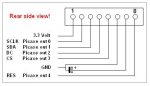
symbol SCLK = 0 'Display pin 2 to PICAXE out 0
symbol SDA = 1 'Display pin 3 to PICAXE out 1
symbol DC = 2 'Display pin 4 to PICAXE out 2
symbol CS = 3 'Display pin 5 to PICAXE out 3
symbol RES = 4 'Display pin 8 to PICAXE out 4
symbol Command = bit0
symbol Value = b2
symbol X = b3
symbol Y = b4
symbol GraphicData = b5
symbol Mask = b7
symbol Loop1 = b10
symbol Loop2 = b11
symbol loop3 = b12
setfreq m8
GoSub Init
GoSub PrName
GoSub Graphic
GoSub Invert
pause 500
GoSub Normal
setfreq m4
Stop
End
Graphic:
X = 10
For Loop1 = 15 To 41
read Loop1, GraphicData
Y = GraphicData / 8
loop3 = -Y * 8 + GraphicData + 7
X = X + 1
Command = 1
GoSub GotoXY
Command = 0
read loop3, Value
GoSub WriteToLCD
Next
Return
PrName:
Command = 0
For Loop1 = 43 To 65
read Loop1, Value
GoSub WriteToLCD
Next Loop1
Return
Init:
'initialisation commands
EEPROM 0,(33,197,6,19,32,12)
'powers of 2 for graphs
EEPROM 6,(0,1,2,4,8,16,32,64,128)
'sine wave lookup table
EEPROM 15,
(24,26,28,30,31,33,34,36,38,39,41,42,43,44,45,46,47,47,47,47,47,47,47
,46,45,44,43,42)
'some characters to display
EEPROM 43,
(127,8,8,8,127,0,32,84,84,84,56,0,124,8,4,4,120,0,72,84,84,84,32)
low SCLK
low SDA
low DC
low CS
low RES
pause 500
high RES
high CS
Command = 1
for Loop1 = 0 to 5 ` start a loop
read Loop1, Value ` read value from EEPROM
gosub WriteToLCD ` transmit to serial LCD
module
Next Loop1
GoSub White
X = 0
Y = 0
GoSub GotoXY
GoSub ClearFast
GoSub Normal
Return
WriteToLCD:
  high DC 'Data mode
  If Command = 0 Then DataMode
    low DC 'Command mode
DataMode:
  low CS
  For Loop2 = 1 To 8
    low SCLK
    Mask = Value & 128
    low SDA
    If Mask = 0 Then Skiphigh
      high SDA
Skiphigh:
    high SCLK
    Value = Value * 2
  Next Loop2
  high CS
  Return
ClearFast:
low SDA
high DC
low CS
For Loop1 = 1 To 48
For loop3 = 1 To 84
low SCLK
high SCLK
Next loop3
Next Loop1
Return
GotoXY:
Command = 1
Value = X + 128
GoSub WriteToLCD
Value = Y + 64
GoSub WriteToLCD
Return
Invert:
Command = 1
Value = 13
GoSub WriteToLCD
Return
Black:
Command = 1
Value = 9
GoSub WriteToLCD
Return
White:
Command = 1
Value = 8
GoSub WriteToLCD
Return
Normal:
Command = 1
Value = 12
GoSub WriteToLCD
Return
Hope this helps,
Texy
I,ve been doing some more experiments today and found that it is incredibly slow to write text - you can literally see the characters being written. I,m using a 18X, and as you can see from the original authers code, he is forcing the 18x to 8meg. I,d prefer not to do that in my final code, but hey.
Before I stumbled upon the picaxe, I had done similair code on the nokia lcd with a 16F88 in assembler, and the 'welcome' text I had at the beginning of the code came up almost immediately. Note that there are no pause commands in the critical part of the code - its going as fast as the code allows. The original author has used the bit-banging examples from manual 2 - is there a quicker way to push out the serial data? I,m wondering if the maths used is slowing the whole process down.
Texy
westaust55
Moderator
Although the code has symbols with the names SCLK and SDA infering i2c comms, at first glance it looks more like basic (no pun) serial bit banging.
Try the SHIFTOUT command (see manual 2 page 159). This certainly works with my 40X1 to shift data into a 74HC595.
in the subroutine WriteToLCD:
In place of the for Loop2 = 1 to 8 . . . . Next Loop2
try:
SHIFTOUT SCLK, SDA, MSBFIRST_L, (Value / 8)
Try the SHIFTOUT command (see manual 2 page 159). This certainly works with my 40X1 to shift data into a 74HC595.
in the subroutine WriteToLCD:
In place of the for Loop2 = 1 to 8 . . . . Next Loop2
try:
SHIFTOUT SCLK, SDA, MSBFIRST_L, (Value / 8)
Last edited:
....not supported by the 18X, so the manual suggests some code...which is being used hereAlthough the code has symbols with the names SCLK and SDA infering i2c comms, at first glance it looks more like basic (no pun) serial bit banging.
Try the SHIFTOUT command (see manual 2 page 159). This certainly works with my 40X1 to shift data into a 74HC595.
in the subroutine WriteToLCD:
In place of the for Loop2 = 1 to 8 . . . . Next Loop2
try:
SHIFTOUT SCLK, SDA, MSBFIRST_L, (Value / 8)
")
Texy
hippy
Ex-Staff (retired)
Not sure why you wouldn't want to use 8MHz. I use it whenever I can, it's as reliable as 4MHz, gives faster execution and adds only a minimal increase in current consumption.as you can see from the original authers code, he is forcing the 18x to 8meg. I,d prefer not to do that in my final code, but hey.
It's not the most efficient code ...The original author has used the bit-banging examples from manual 2 - is there a quicker way to push out the serial data? I,m wondering if the maths used is slowing the whole process down.
Code:
WriteToLCD:
high DC 'Data mode
If Command = 0 Then DataMode
low DC 'Command mode
DataMode:
low CS
For Loop2 = 1 To 8
low SCLK
Mask = Value & 128
low SDA
If Mask = 0 Then Skiphigh
high SDA
Skiphigh:
high SCLK
Value = Value * 2
Next Loop2
high CS
Return
Code:
WriteToLCD:
  high DC 'Data mode
  If Command = 0 Then DataMode
    low DC 'Command mode
DataMode:
  low CS
  For Loop2 = 1 To 8
    low SCLK
    [b]SDA_PIN = bit7[/b]
    high SCLK
    Value = Value * 2
  Next Loop2
  high CS
  Return
Code:
WriteToLCD:
  high DC 'Data mode
  If Command = 0 Then DataMode
    low DC 'Command mode
DataMode:
  low CS
  For Loop2 = 1 To 8
    SDA_PIN = bit7
    [b]PulsOut SCLK,1[/b]
    Value = Value * 2
  Next Loop2
  high CS
  Return
Code:
[b]WriteCommandToLCD:
  Low DC
WriteDataToLCD:[/b]
  Low CS
  For Loop2 = 1 To 8
    SDA_PIN = bit7
    PulsOut SCLK,1
    Value = Value * 2
  Next Loop2
  High CS
  [b]High DC[/b]
  Return
Code:
WriteCommandToLCD:
  Low DC
WriteDataToLCD:
  Low CS
  [b]SDA_PIN = bit7 : PulsOut SCLK,1
  SDA_PIN = bit6 : PulsOut SCLK,1
  SDA_PIN = bit5 : PulsOut SCLK,1
  SDA_PIN = bit4 : PulsOut SCLK,1
  SDA_PIN = bit3 : PulsOut SCLK,1
  SDA_PIN = bit2 : PulsOut SCLK,1
  SDA_PIN = bit1 : PulsOut SCLK,1
  SDA_PIN = bit0 : PulsOut SCLK,1[/b]
  High CS
  High DC
ReturnTo get maximum speed, using the on-chip SPI hardware where available is the best approach. The 28X1 and 40X1 support that and the 18X can be coerced into doing it with a bit of SFR jiggery-pokery. It may mean having to re-allocate your I/O lines to do that but the speed gains will be quite phenomenal.
Mmmmm...nor do INot sure why you wouldn't want to use 8MHz. I use it whenever I can, it's as reliable as 4MHz, gives faster execution and adds only a minimal increase in current consumption.
- the speed is there, so why not use it?....yep I already done that bitIt's not the most efficient code ...
There's plenty of scope for optimisation there. The use of MASK can be avoided by making 'value' to be b0 or b1 then using bit7 or bot15 for fast access to the msb. Note 'command' is bit0 so that may need to be moved. With that done, SDA can be SYMBOL SDA_PIN = pin1 and SDA_PIN = value giving ...Code:WriteToLCD: high DC 'Data mode If Command = 0 Then DataMode low DC 'Command mode DataMode: low CS For Loop2 = 1 To 8 low SCLK Mask = Value & 128 low SDA If Mask = 0 Then Skiphigh high SDA Skiphigh: high SCLK Value = Value * 2 Next Loop2 high CS Return
If it's not necessary to lower SCLK before setting the data ( I'm not familiar with ths LCD ) the LOW/HIGH SCLK can become a fast PULSOUT ...Code:WriteToLCD: high DC 'Data mode If Command = 0 Then DataMode low DC 'Command mode DataMode: low CS For Loop2 = 1 To 8 low SCLK [b]SDA_PIN = bit7[/b] high SCLK Value = Value * 2 Next Loop2 high CS Return
The routine can be split into two, one to write data, the other to write commands. Data is sent more frequently so that should be the fastest ...Code:WriteToLCD: high DC 'Data mode If Command = 0 Then DataMode low DC 'Command mode DataMode: low CS For Loop2 = 1 To 8 SDA_PIN = bit7 [b]PulsOut SCLK,1[/b] Value = Value * 2 Next Loop2 high CS Return
THAT is a good idea - I will try that next!Finally, for maximum speed the FOR-NEXT loop should be unrolled, which also removes the time taking multiply ...Code:[b]WriteCommandToLCD: Low DC WriteDataToLCD:[/b] Low CS For Loop2 = 1 To 8 SDA_PIN = bit7 PulsOut SCLK,1 Value = Value * 2 Next Loop2 High CS [b]High DC[/b] Return
All untested, but that's how I'd approach it.Code:WriteCommandToLCD: Low DC WriteDataToLCD: Low CS [b]SDA_PIN = bit7 : PulsOut SCLK,1 SDA_PIN = bit6 : PulsOut SCLK,1 SDA_PIN = bit5 : PulsOut SCLK,1 SDA_PIN = bit4 : PulsOut SCLK,1 SDA_PIN = bit3 : PulsOut SCLK,1 SDA_PIN = bit2 : PulsOut SCLK,1 SDA_PIN = bit1 : PulsOut SCLK,1 SDA_PIN = bit0 : PulsOut SCLK,1[/b] High CS High DC Return
I will look into that, although I,m already using the I2C bus.To get maximum speed, using the on-chip SPI hardware where available is the best approach. The 28X1 and 40X1 support that and the 18X can be coerced into doing it with a bit of SFR jiggery-pokery. It may mean having to re-allocate your I/O lines to do that but the speed gains will be quite phenomenal.
Thanks so far, I will report my findings. Its a pity that the simulater doesn't
have a stopwatch/timer function as in MPLAB to check times/machine cycles.
Texy
westaust55
Moderator
Bit of a "nuisance" that the 18X (and other non X1 parts) does not support SHIFTOUT.
I have just tried the SHIFTOUT command versus program bit-bang method and found the SHIFTOUT command to be ~7 times faster.
Look at my test code in thread:
http://www.picaxeforum.co.uk/showthread.php?t=9831 in Post No 3
and seems that the ‘hspiout’ command could be faster still
I have just tried the SHIFTOUT command versus program bit-bang method and found the SHIFTOUT command to be ~7 times faster.
Look at my test code in thread:
http://www.picaxeforum.co.uk/showthread.php?t=9831 in Post No 3
and seems that the ‘hspiout’ command could be faster still
Last edited:
hippy
Ex-Staff (retired)
HSPIOUT can be faked on the 18X by poking the right SFR's. There's a post somewhere about doing that. Using I2C does present a problem though as SPI and I2C both use the same I/O pins. Some diode mixing / clamping to select between I2C and SPI could work there; force I2C SCK high and it'll never see a Start Bit, clamp SPI CLK low and the LCD will never clock data in. Both are uni-directional lines so should work ...
SEL = 1, SPI Enabled
SEL = 0, I2C Enabled
Maybe not ... The diode from SCK to I2C SCK is the wrong way round, but there's probably some solution to be had along those lines.
Code:
                             --.--
                              .|.
.-------.                     |_|
|       |                      |
|   SCK |----.----|>|----.-----^-----> I2C SCK
|       |    |    ___    |
|       |    `---|___|---|-----.-----> SPI CLK
|       |                |     |
|   SEL |----.----|>|----'     |
|       |    |                 |
`-------'    `----|<|----------'
SEL = 0, I2C Enabled
Maybe not ... The diode from SCK to I2C SCK is the wrong way round, but there's probably some solution to be had along those lines.
Last edited:
Well all of the above code tips have helped to make things noticeably faster and 'good enough' for me, so I,m not planning on any hardware changes.HSPIOUT can be faked on the 18X by poking the right SFR's. There's a post somewhere about doing that. Using I2C does present a problem though as SPI and I2C both use the same I/O pins. Some diode mixing / clamping to select between I2C and SPI could work there; force I2C SCK high and it'll never see a Start Bit, clamp SPI CLK low and the LCD will never clock data in. Both are uni-directional lines so should work ...
SEL = 1, SPI EnabledCode:--.-- .|. .-------. |_| | | | | SCK |----.----|>|----.-----^-----> I2C SCK | | | ___ | | | `---|___|---|-----.-----> SPI CLK | | | | | SEL |----.----|>|----' | | | | | `-------' `----|<|----------'
SEL = 0, I2C Enabled
Maybe not ... The diode from SCK to I2C SCK is the wrong way round, but there's probably some solution to be had along those lines.
Thanks again guys as I,ve learned some good coding tips
Texy
It is possible to mix SPI and i2c on the same system without resorting to diodes etc. This is well documented and the only proviso is that you don't try to do both at the same time!
The chip select isolates the SPI operations and the i2c read/write isolate the i2c operations.
The chip select isolates the SPI operations and the i2c read/write isolate the i2c operations.
Code:
[B][COLOR=#ff0000]I2CChip.com: [/COLOR]Mixing I2C and SPI on the same pins:[/B]

[B]Contents[/B]
[LIST]
[*][URL="http://www.i2cchip.com/mix_spi_i2c.html#Summary"][COLOR=#0000ff]Summary[/COLOR][/URL]
[*][URL="http://www.i2cchip.com/mix_spi_i2c.html#Other Serial Devices for Expansion"][COLOR=#0000ff]Other Devices[/COLOR][/URL]
[*][URL="http://www.i2cchip.com/digital_display_module.html#contents"][COLOR=#0000ff]4 Digit Display Modules[/COLOR][/URL]
[*][URL="http://www.i2cchip.com/index.html"][COLOR=#0000ff]Back to Home[/COLOR][/URL][/LIST]Graham North wrote "[I]Is there such a thing as an SPI port expander?
I know there [/I][I]is such an I2C > device (I2C Parallel port). As I am
running out of I/O and the [/I][I]design uses > SPI peripherals[/I]"
[B]You can normally mix I2C and SPI on the [/B][B]same pins with
no problems.[/B]

You can normally mix I2C and SPI on the same pins. I2C only
does something [I][B]between[/B][/I] START and STOP.
START is when SCL is HI, SDA goes to HI->LO.
STOP is when SCL is HI and SDA goes LO->HI.
So if you arrange your code such that SDA only changes value
when SCL is LO, there will be no problems. The I2C will not
notice any SPI transactions. Of course all the SPI devices have
thier own individual CS pin, but this is the disadvantage of SPI.
So to spell it out.
[LIST]
[*]You can use I2C devices on an SPI bus. Just connect SCL to
SCLK and SDA to SDIO.
[*]You can use SPI devices on an I2C bus, just give each chip
its own CS signal.
[*]Between START and STOP you can only do I2C transactions.
[*]The bit timing will be set by the I2C bus,even when doing SPI,
ie use 100 or 400kHz
[*]Write your routines so that SCL and SDA don't change at the
same time. This also removes the problem of SPI devices with
rising vs falling clock
[*]The "SPI" type devices do have to have a common-able data
in and out pins.
[*]You can use the same routines for both if you are short of code
space. Some SPI devices will need non 8 bit sized transfers.
[*]I2C devices have noise filters on the input. SPI devices don't.
Bear this in mind if you have long cable runs.
[*]You will need to have a reset function that makes sure everything
is in the correct state. In particular, some non-I2C serial devices
needs some clocks to bring them into a defined state.[/LIST]
Last edited:
For any Brits that may be interested,
now that the hard work on the code has been done!
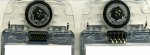
I've just received four Nokia LCD's, from an ebay seller.
£4.02, including postage.
Brass(?) springy-legs on the back. I've bent back four of the legs,
to make soldering a bit easier.
One day, I might finish it.
e
now that the hard work on the code has been done!
I've just received four Nokia LCD's, from an ebay seller.
£4.02, including postage.
Brass(?) springy-legs on the back. I've bent back four of the legs,
to make soldering a bit easier.
One day, I might finish it.
e
Attachments
-
 184.3 KB Views: 30
westaust55
Moderator
e,
are these the same Nokia 3310 type displays or fomr a differnet model?
are these the same Nokia 3310 type displays or fomr a differnet model?
Four for £4 ? Blimey, I paid £3 for 1 off ebay a couple of months back.For any Brits that may be interested,
now that the hard work on the code has been done!
I've just received four Nokia LCD's, from an ebay seller.
£4.02, including postage.
Brass(?) springy-legs on the back. I've bent back four of the legs,
to make soldering a bit easier.
One day, I might finish it.
e
Doing a search now seems to show the same prices?
Do you have a link to the seller?
Texy
OK, I found it -
http://cgi.ebay.co.uk/NOKIA-3310-3330-NEW-ORIGINAL-LCD-SCREEN_W0QQitemZ200228401835QQcmdZViewItem?_trksid=p3286.m20.l1116
29pence each, plus £1.99 postage, then add (29+29=58) for each additional screen !!
Texy
http://cgi.ebay.co.uk/NOKIA-3310-3330-NEW-ORIGINAL-LCD-SCREEN_W0QQitemZ200228401835QQcmdZViewItem?_trksid=p3286.m20.l1116
29pence each, plus £1.99 postage, then add (29+29=58) for each additional screen !!
Texy