AXE 133Y problems

russbow

Senior Member
I have been using a 433MHz link for some time with no problems. Moving it to an enclosure with a dedicated AXE 133Y display caused a malfunction so I assumed I had broken something.

In the end I loaded this code into the transmitter :-

Code:
'18m2 
'17/07/12

#picaxe18m2


b0=0

do
	b0=b0+1
	gosub sendit
	pause 5000

loop

sendit:	

	high c.2
	setfreq m4
	SerOut c.2,T600_4, ("UUUUU")  'wake up Rx
	serout c.2,T600_4,($AA, $BB, $CC,b0)		'Output data to TX
	low c.2
return
And this in the receiver module.

Code:
'18m2 
'17/07/12

#picaxe18m2


symbol LCD=b.4
symbol ANT=c.1

serout lcd,n2400,(254,1)	'CLS

	b1=0

do
	b0=1
	gosub Rec
loop

Rec:

	serin ANT,T600,( $AA, $BB, $CC ),b0 'Get data
	pause 100

	serout LCD,N2400,(254,128,"Count = ",#b0)	'Display it
	serout LCD,N2400,(254,192,"Loop ",#b1)
	
	if b0=255 then let b1=b1+1	'Increment loop counter
	endif

	sertxd ("Count ",#b0,cr,lf)	'Also send tp PC screen
	sertxd ("Loop ",#b1,cr,lf)
	
return
Without the display connected, sertxd shows expected results. Connecting the display - even just the neg and pos - causes the Rx to stop.

Supply volts measure 4.99 volts without the display and 4.97 volts with the display

Moving the picaxe output to my "static" AXE 134, (20x4) unit on my development board produces perfect results. The 20x4 follows sertxd faithfully.

The AXE 133 "suspect" unit works perfectly on all my other projects.

:confused:

Russ
 

nick12ab

Senior Member
First of all, have you got a decoupling capacitor and a bulk capacitor on your receiving circuit?

If yes, then swap the displays attached to the AXE132s around and see if the 'suspect unit' is still the module with the 16x2 display or whether it is now the one with the 20x4 display.
 

russbow

Senior Member
Yes Nick, Rx unit fully de-coupled and "smoothed" .
Both displays powered by same supply. Just a matter of swapping over the OLED input pins.

I've just noticed that when it runs OK on the 20x4, connecting the suspect unit across the supply, then the "good one" stops.

Obviously a problem with the 2x16, but this is ok on other projects. Shall power it up from separate batteries and see what happens.
 

nick12ab

Senior Member
Have you tried:
  • Connecting the suspect 16x2 module with its 18M2 removed
  • Swapping the OLEDs around (i.e. 20x4 OLED display is now attached to the AXE032 that the 16x2 OLED was connected to and vice versa
 

russbow

Senior Member
Can't do that Nick. All "built in". However, got to be a de-coupling problem. When I drive the 16x2 with a separate battery pack, all is well.

Need to dig deeper. Keep you informed.

R.
 

AllyCat

Senior Member
Hi Russ,

Could it be Radio Frequency Intererence of a harmonic of the OLED's processor clock into the 433 MHz receiver? If so, a reasonably large change in the processor's supply voltage or temperature should produce a change of more than say 0.1% and take it "out of band". If it's being carried on the supply rail, you might need to add quite a small decoupling capacitor to filter it, perhaps 1nF or less, preferably ceramic.

Cheers, Alan.
 

g6ejd

Senior Member
If RFI is suspected, which may be a long shot, as the source feed of the RFI would still be present even on separate battery supply; then you could add a series inductor (choke) in the supply line of the display, that may help reduce any RFI.

The displays can take a quite a bit of supply current, is your supply really adequate? Is one display LCD with back-light and the other OLED, the current consumption can be orders of magnitude different (higher) for LCD.
 

russbow

Senior Member
Did wonder about RFI but I think not.Placing the RF module on top of the display does not cause any problem.
The display is the Rev Ed OLED kit.

Must be a de-coupling problem as all is well if Picaxe / RF are powered from the main regulated supply and the display by batteries.
Fails if all are powered by the same supply ( main regulated OR batteries ).

Going QRT for a few days so will let you know the outcome later.

Thanks,

Russ
 
Last edited:

russbow

Senior Member
Always give it the "Look Test"

Unbelievable. All my development modules are built like this.

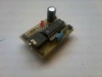
18m2.jpg

Somewhat blurry phone snap. They plug onto the breadboard and pick up the power from the BB rails.
This 18m2 add on has been working for more than a year and has powered a number of projects.

Becoming convinced that the tale of woe above was a de-coupling problem, I gave the plug-in a good look test.

The electrolytic was soldered in the wrong way round.

Defies all logic. Worked on all projects, even any with a 20x4 OLED, until connected to the smaller 16x2 OLED.

Happy to say, all is now OK.
 
Last edited:
Top