Yep - it's interesting. But just 'cos it's on the Internet doesn't mean it's right/the best/the most efficient in parts count/the most efficient in cost etc etc.
The whole idea was to come up quickly with something inexpensive, using parts commonly available here in the States, that would greatly reduce the likelihood of PICAXE "glitching" or over/undervoltage with Pilko's specified load voltage and current.
In the USA, we have "Radio Shack" stores in most towns and cities with even a moderately-sized population. Many "n00bs" are impatient to get their projects going, and if they have to wait for a week or more to get parts via the mail, they might just say the heck with it and try it without any such protection; which usually leads to very poor results.
I like some parts of it and not others:
- not reverse connection proof
If someone cannot tell the difference between a wire and the frame of an automobile, perhaps electronics is not a hobby they should pursue.
Besides, the output required was 9v from a 7809 regulator, which has a minimum 2v dropout at no load, from an automotive system that might drop to 11v or even lower. There really wasn't enough "headroom" to add such protection. However, the fuse would likely blow before causing real damage.
- not an automotive spec regulator
Many n00bs wouldn't bother to use an automotive-spec PICAXE, either. You'd be doing good to convince them to use an industrial-spec uC.
- doesn't obey the LM317 data sheet in terms of output capacitance
Ah. Here's the datasheet:
http://www.national.com/ds/LM/LM117.pdf
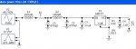
Look at the left column, bottom of page 9. Note the reference of 500pF to 5,000pF (5nF, 0.005uF) causing ringing. 0.1uF is 20x that amount, which should be sufficient to swamp the ringing. Note that the schematic I posted is the minimum that's required; the 0.1uF cap is right at the output of the regulator.
But really, it's out of context anyway, since it was stated in the text of the thread (that you apparently did not read) that the LM317 and two resistors were a substitute for the 7809 regulator that the original requester, Pilko, stated they were going to use. If you care to peruse datasheets for the 78xx series of 1A positive regulators, you will note that they require 0.33uF input and 0.1uF output caps, which ARE present in the schematic.
- 1421R resistor...err...
If you'd read the part about the 317 being used as a substitute for the 7809 because I didn't have a model for it loaded in the library, you
might have understood that the 120 Ohm and 1421 Ohm resistors were representing those internal to the 7809 regulator.
- I like the 100uH and the 5R resistor...
- ...but two 100uH/470uf low pass filters is waaay over the top
Not really, when you consider that some transients will be quite large and longer in duration than the simulation.
- and if he thinks that designing a circuit to eliminate 40Vp-p 3KHz AC is all that is needed in an automotive supply, then he doesn't think enough
Funny; first you complain that the filtering is overkill, then you complain that the transient analysis is insufficient.
Getting back to what I said in the beginning, it was something to meet Pliko's immediate needs using easily sourced parts that would be inexpensive, and would give his project a much better chance of survival than what a typical hobbyist might use - just a 7805 with no input or output caps.
What I find ironic is that in one of your past posts, you posted a link to AllAboutCircuits regarding 7805 regulators in which I had tested a series of those regulators, and found a couple of them that oscillated in the MHz range without the bypass caps, and indicated that 0.1uF caps took care of it.
So previously, you used me as a reference, and now you attempt to criticize a schematic which actually IS in compliance with the specifications of the actual regulator that was to be used.
You also failed to note that in the thread about THIS schematic, I explained that it was not an optimized solution.
It's more of a "field expedient".
Could do better. I give it a C.
I say old chap, had you done more than glance at the schematic and taken things quite out of context, the grade would have been a bit better.
Meanwhile, failure to read and correctly interpret the accompanying text in the thread gives you a very kind C-

(you're not SgtWookie I trust?
)
He wasn't. I am.