Automatic LED brightness control?

212

Senior Member
I have a little black and white video camera, and I want to add some IR LEDs to light up the night. I would like to have them adjust down when something is real close to the camera...usually it will just white out the picture. BCJKiwi was kind enough to explain how to auto-adjust the brightness of an LED with this code:

main:
readadc10 4,w1
pwmout 2, 99, w1
goto main

I am grateful for the help too...thanks again. But I want the LEDs to dim when the light gets too bright...this works opposite...the brighter the light gets the brighter LEDs get. After searching, and reading a lot of unrelated but interesting things, I never found what I needed to learn.

I used my 08M school experimenter board to try it, is there another way to use the LDR..or another way to write the code???

Oh, I found out my hearing is not as good as my wife's...I could not hear the speaker till she came in complaining about the loud squeal coming from in here ...:rolleyes:


edit: How come I think of things after asking for help???

if w1 = this then PWM that....but this sure will be a long code huh. Anything better???
 
Last edited:

SD2100

New Member
Try flipping your voltage divider circuit upside down, instead of the LDR going to 5v and the resistor to 0v connected the LDR to 0v and the resistor to 5v
 

inglewoodpete

Senior Member
An easier solution would be to do the same thing in software:
Code:
main: readadc10 4,w1
      w1 = 1023 - w1
      pwmout 2, 99, w1
      goto main
 

212

Senior Member
Thanks for both suggestions! I just tried changing the code, and it worked...but I have to have the LDR right up to a light for it to dim. I guess I would need to change the resistor value??? I'll try the voltage divider circuit upside down and see what that does too.
 

inglewoodpete

Senior Member
Once again, there are both hardware and software solutions.

I would persue the software solution: it is easier to switch code around than to swap components. The software solution will involve changing the mathematical formula used to change the value read (via ReadADC) into the value used via (PWMOut).

The formula used will depend on the useful ranges of values being read (Eg 'dark' may equal any value in w1 under 250) and being output as PWM (Eg Values under 450 may be ineffective). The formula could add, subtract, multiply or divide the input value. It will be a matter of experimenting. The Min and Max operators will be useful to limit the values, too.

An example of what you could try is:

w1 = 1023 - w1 * 15 / 10 Max 1023
 

212

Senior Member
This can get fun :) I did try changing the divider and it works better with what I have. Now I want to play with the code again with the new example too.

By the way, what does the 99 mean in pwmout 2, 99 that the PWM wizard gives out???

And thanks!!!
 

BCJKiwi

Senior Member
The divider is the initial setting that needs to be sorted out.

While adjustments can be made in software, its better to get the range right in hardware, that way you don't find the circuit working all at one end of the range.

Basic method recommended (by the Dr I Think) is to measure the R of the LDR at the mid range of the light level you are interested in. Make the divider R the same as this. This puts the ADC V to be read right in the middle of the range of interest.

LDRs are not linear either so further adjustment is usually needed.

If you want you could use a Pot for the divider R until the value is established then change it for the nearest fixed value R.

Once this 'coarse' adjustment has been made, tweak the final values in software.

As for the 99 - check the manual and the PWM wizard so you have an understanding of what you have to work with when changing the values in your program.
 

westaust55

Moderator
I concur with BCJKiwi.

First you really need to find out:
a) specs for the LDR you have
b) the range of light levels you will work in
c) have an idea how (b) varies the LDR resistance.

I did some calcs and actual tests months ago. Have a look at this thread:
http://www.picaxeforum.co.uk/showthread.php?t=9265

For that thread I was endeavouring to maximise the input voltage to an ADC pin and lookin for the optimal resistor value albeit that some come out to be higher than may be considered optimal in terms of meeting the max 10kOhm impedance to the ADC inputs.
 

212

Senior Member
You guys were too easy on me on that last question. My reply to myself, after I had already hit the button, was READ THE MANUAL....see...it needed to be capitalized. I really appreciate the help, and yes, I will read up on this stuff.

westaust55, somehow I totally missed that topic??? Thanks for the help!
 

boriz

Senior Member
The LDRs spectral sensitivity is fairly close to that of the human eye. So I don’t know how well it responds to IR light. Just thought I’d mention it. Could be a factor.
 

westaust55

Moderator
LDR's used with IR light

Good point Boriz.
And a very significant factor – at IR wavelengths the response has dropped of very dramatically
Infrared radiation has wavelengths between about 750 nm and 1 mm. Datasheets I have available for LDR’s all indicate the Cadmium Sulphide type work best around 520 nm wave length.
Have a look at the attached datasheet for ORP12 type LDRs
 

Attachments

Last edited:

westaust55

Moderator
I did not have a PVD-P9 series datasheet at hand but the PVD-P8 series indicates max response at 520 nm wavelength so similar to the OPR12. Both PVD-P8 and PVD-P9 state an upper limit of 700nm.

I would consider the PVD range generally similar to the OPR12 type so a lower response (resistance variation) under IR light.
You originally stated: “But I want the LEDs to dim when the light gets too bright”

Is this both visible light and IR light?

I suggest that you do some tests with the intended IR source and measure the resistance variation you will get from light to bright conditions.
Visible spectrum light will likely cause a more significant change, but if I understand correctly, that is still in line with what you are wanting.

If may come down to defining what value is deemed as bright under visible light and what value is deemed bright under IR light (which from an analogue input value could be about half the visible value).
Once you know what the hardware does, then you can adjust the software to suit.
 

212

Senior Member
Yes, I am wanting to use the same circuit for both visible and IR. I will test the resistance. I think this should still work, but I'll need to do some cyphering huh. In fact...this may be perfect. I don't even need the light on at all till it gets twilight...that's easy enough. The tricky part will be adjusting the LED output according to how much reflected IR light it sees....there will not be much of it.
 

inglewoodpete

Senior Member
Further to WA55's reply, I suggest the following.

Modify the basic code to something like:
Code:
main: readadc10 4,w1
      w2 = 1023 - w1   'Experiment with this equation
      pwmout 2, 99, w2
      Debug            'Send values to PE debug scrren for observation/analysis
      Pause 5000       'mS
      goto main
You will need to determine what threshold (natural) light value is the point where you need infill IR lighting. Then, of course, you need to determine a relationship between the artificial light vs various levels of natural light. That part is really in your hands.
 

212

Senior Member
inglewoodpete, that is very cool! I put that into the school experimenter and it actually shows what it going on :) I have read about this before, but never had tried it myself. This is going to help a LOT...after I add the proper download circuit to my project. (should have done that from the start huh)
 

boriz

Senior Member
“I have a little black and white video camera” No AGC?

Can’t you derive the image brightness from the image itself? Or from the camera?
 

212

Senior Member
Posted at the same time boriz...

Yes it has AGC, but it will white out an animal if it is within about 3~4 feet....because the light is so bright.


Thank you all for the replies and help! I added the download circuit to my camera set-up, but guess what.
.
.
.
.
I used pin 0 to turn on my LED mosfet....doh

I'm going to be building another version soon though, and will pay attention to how I build it this time :)
 
Last edited:

212

Senior Member
"Can’t you derive the image brightness from the image itself? Or from the camera?" Sure can't...how do I do that??????

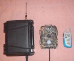
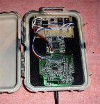
I did not go into a lot of detail when asking the question. Here is a shot of the set-up. It uses an ex-view camera now, 14 BRIGHT IR LEDs, has a motion detector to activate it, transmits audio and video over 900 MHz to my house from the creek, has an FRS to signal me when active, and I can turn on the camera when I want to watch it too. The next one will have two cameras...one color for daytime, and an ex-view for night. Yes I'm addicted to cameras and Picaxe :)
 

Attachments

Last edited:

boriz

Senior Member
Like it!

Couple of options off the top of my head:

1 – Use an IR phototransistor with some amplification. It will probably become swamped during daylight. But that’s fine coz it just means the IR LEDs will be off.

2 – Use one of the IR receiver/demodulator units used with INFRAIN. The IR LEDs will need to have a PWM frequency of 38Khz, though duty can vary. The receiver is very sensitive and will easily pick up reflected IR light, but reject ambient light. In fact it might be over sensitive for your needs. You may need some additional optical filtering.
 

212

Senior Member
Thanks, I'll surely pick up a couple of those today. Last night I had an idea too. I have a few photodiodes used for a slave flash trigger, so I decided to see what happened using them. I just put the positive lead to pin 4 and grounded the other. Now I have no idea what I'm doing here, and it's OK to laugh, but I tried this...and it did work somewhat:

main: readadc10 4,w1

w2 = w1 + w1 + w1 + w1 + w1 + w1 + w1 + w1 + 400 max 1023
W3 = 1023 - w2 'Experiment with this equation
pwmout 2, 99, w3
'Debug 'Send values to PE debug screen for observation/analysis
'Pause 3000 'mS
goto main

It sees the IR light very well too! http://www.everlight.com/upload/product_pdf/PD333-3C-H0-L2.pdf
 

inglewoodpete

Senior Member
212, You're on the right track.

It would be wise to put a resistor in series with each IR LED to stop it/them damaging the PICAXE output drivers.

Also,
w2 = w1 + w1 + w1 + w1 + w1 + w1 + w1 + w1 + 400 max 1023

could be represented as
w2 = w1 * 8 + 400 max 1023

This formula suggests that you are reading quite a small input voltage on the LDR/Resistor junction (you are multiplying a small value by 8 and adding 400). This will affect your the resolution (size of the steps) of the values you are reading. Experiment with the resistance size to bring the voltage up towards mid-range (+2.5v) for 'normal' conditions. If you change the resistor value, you will need to change your formula, of course.
 

212

Senior Member
I went to one store, and they did not have the receiver module. They looked on the computer and told me of one store that showed two, and another showing 5 in stock. None of them really had any though :(

Sooooo...last night I played with the photo-diode some more, with the diode positive to pin 4 and the negative to ground. And...I did some reading about how to write the code too. I saw that the ( * ) means times, yep, just like you show there. Maybe I'm not using the photo diode right??? But...it would work the way I have it, except that the reading dances around, making the LED go bright and dark... often.

I did a lot of experimenting with the PWM, and with the math, and even tried sticking different caps in the circuit. If I connect one of the photo-diodes directly to my volt meter, it does the same thing....it shows about 580 millivolts in direct sun, about 300 in a bright room, and somewhere around 70mv in the dark with only the computer screen lit. The reading jumps around about 4~5mv whether in the sun or the dark, but when multiplied it makes a big difference in the LED brightness at night. I am using a mosfet, now, to power the LEDs, but it does this either way.

I'll look for info on how to use a photo-diode properly, maybe that's the problem...
 

fernando_g

Senior Member
212;
photodiodes produce very tiny amounts of current, and have several error sources, like dark current, that must be accounted for. Getting a linear output is simple but not trivial.
You'll need assitance from that ubiquitous analog building block: The opamp.

The following link shows how to do it. http://www.national.com/onlineseminar/2004/photodiode/PhotodiodeAmplifers.pdf
Stick to the photovoltaic mode, it is simple and as fail-safe as it can be.

The only real requirement is to properly select the opamp. A plain vainilla device like the LM358 is no good. But there are now many improved precision devices that won't cost you an arm and a leg. I have personally used the TLC2272 with very good results, it also features rail to rail for both input and output, which is a bonus if you want to realize the full A/D dynamic range. DigiKey lists them at US $1.38 in single quantities.

I like this opamp so much, that I use it as the analog front end in all my PICAXE projects that have required analog signal conditioning.
 
Last edited:

212

Senior Member
He just wanted to make you mad is all lol...

OK....I'll have to order the TLC2272, I have a bunch of other stuff on the list too. In the mean time, I started just trying different ways to use what I already have. I'll do it the right way when I get the parts, but this seems to work pretty decent. In the dark it goes up to around 250, and most of the dancing around was below 20. If this isn't going to cause some huge issue, I think I might play with the code some more...just how bad is this wrong???

main:
readadc 4, w1
pwmout 2, 99, w1

debug
pause 600
goto main
 

Attachments

Last edited:

fernando_g

Senior Member
boriz;
It is not that I got something "against" the LM358. I've used it countless times myself, and its a great amp for its price.

But for this application it has a drawback: its maximum output voltage is 1.5 to 2 volts below the supply voltage. This means that in a 5 volt supply your maximum output voltage will be in the whereabouts of 3 to 3.5 volts. In ADC10 counts, this means it could be as low as aprox 615 counts.
Whether or not this is important, depends on the application. Since poster 212 is dealing with a large dynamic range, I think it is worthwhile.

A parameter like input resistance, which is not properly specified on the LM358, but on the TLC2272 is 10^12 ohms. Again, it all depends on the application. I have had in the past circuits that misbehave, and after lots of headaches have been traced to lower-than-expected opamp input impedance. Photodiodes really thrive in high impedance environments when operated in the photovoltaic mode.

The TLC2272 has other advantages too; its slew rate is about 10 times faster than the LM358. Not really important in this application. However, I once required to precision-rectify the waveform from a switch mode PSU. The LM358 simply could not cope with it, the TLC2272 did.

In conclusion... just like one would rather use a 08M instead of a 28X1 to handle a a few flashing Led's, the LM358 and TLC2272 each have its own application segment.
 

LizzieB

Senior Member
I'll give a thumbs up to using a more modern part too. My favorite is the TLV2472 which is similar to, but for my purposes just a bit better than, the TLC2272. I have used it many times in single supply photodiode amps in the photovoltaic/current to voltage converter mode suggested by fernando.
 
Last edited:

lbenson

Senior Member
LizzieB--as guidance for hobbiests, can you sumarize what you find superior about the TLV2472 with respect to the TLC2272? I know, read the datasheets. But I've only used an opamp once, following suggestions, and it's hard to know just what one is looking for in the datasheets.

LSB--once myself called Lizby by some
 

LizzieB

Senior Member
I agree, datasheets are very confusing. Nothing ever seems to be specified the same way making it difficult to compare parts. Also the only numbers that are really worth anything are minimums and maximums (and not all of those are actually tested on all production parts). Typical values were probably established back on some pre production run and never updated.

In this case I should have added "IMHO" and I'll edit that posting. It depends on what you are looking to use the parts for. For me I appreciated the lower supply current and slightly higher speed of the 2472, but someone else may appreciate a particular parameter of the 2272. They are both great parts.
 

212

Senior Member
I have a question concerning this:

readadc10 4, w1
pwmout 2, 99, w1

If w1 can go up to 1023...and the wizard says pwmout 2, 99, 400 is 100 percent...that just don't make since to me???? Please explain????
 

BeanieBots

Moderator
The last two numbers in PWMout are period and duty.
They are related to each other. Duty must not be more than four times period.
So, if you want the maximum range of duty (1023) you must use the maximum value of period (255).

Hence,
readadc10 4, w1
pwmout 2, 99, w1

could give unexpected results if readADC returns a value greater than 396.
 

inglewoodpete

Senior Member
Yes, you're right 212. An oversight by both of us? I just copied your code from the first post.

The options are to either restrict the range of w1 or bump up the period parameter to 255.

Of course, if you're going to use 38kHz PWM, the period value will be dictated by the PWM wizard and the duty_cycle parameter will need to be proportionate to that.
 

212

Senior Member
Whew! thanks for explaining that to me. That confirms what I was thinking, but being what I am, I had my doubts. ;)
 

inglewoodpete

Senior Member
I just ran the PWM frequency of 38kHz in the PWM wizard and it gives
Code:
PWMOut pwmpin, 25, 11     ' 10% duty cycle at 38,000 Hz
PWMOut pwmpin, 25, 105    '100% duty cycle at 38,000 Hz
This tells us 2 things: resolution will be about 1% and no need to use ReadADC10. ReadADC command into a byte will give more than enough resolution.
 

212

Senior Member
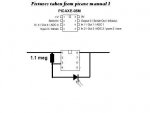
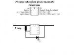
I'm pretty hard headed, and thick too, so I've been playing with just the photo-diode, without the op-amp, till I get one here. I kept adding 1 meg resistors to this, and the level at which the LEDs get to full brightness kept getting closer to to where I wanted it. The biggest single resistor I have is about 7 meg, and it is fairly close to working perfect. I have tried everything I could think of to try, to get the code to move the range at which the LEDs show full brightness, but so far not to successfully. I did try readadc and did try 38khz, but not both at the same time...yet.

I find that the point at where I need the LEDs to dim is very close to the point where they need to be on fully. Even if this is wired wrong, at least I'm learning from it. I'm using a 140 IR LED array for testing, but I think the ones I have in the camera case put out about the same amount of light. Right now, I have the camera down at the creek watching over some old bread I threw out, and a little trough of fresh water. When one of the critters gets within about 3 feet of the camera, it gets too bright for the AGC to compensate for. That's what I need to fix with this....can't have them using the light to stay warm all the time either you know lol...

Thank you guys for the help so far :)
 

Attachments

Last edited:

BeanieBots

Moderator
As a VERY general guideline to resistor value (in ANY circuit)
If you need < 100R or > 100k then think carefully.
< 10R or > 1M then you WILL need to consider some lesser obvious effects.
(leakage, noise, input impedances and many others.

Hence, your 7M is an indication that another approach needs consideration.
Namely the op-amp method discussed. At such high resistances your circuit will be very prone to noise and temperature effects.
 
Top