Autodetect of URF and ERF modules ?

pkf

Member
Hi, I am trying to find out the usage of RFA030.
I pluggged in the URF module to the PC, and installed the URF driver successfully.
Then I assembled the ERF module to the Microbot.
When I started the Picaxe Editor, it was able to detect the URF module. However, when I tried to download a program through the modules, it reports a COM error. What should I do next ?
 

hippy

Ex-Staff (retired)
What was the wording of the COM error you received ?

How do you have the ERF connected to the MicroBot ?
 

pkf

Member
The wording of the COM error was :
Hardware not found on COM9!

I know there is a solution on soldering to connect the ERF to the Microbot.
The original solution was pin 2 to the stereo jack body, pin 3 to the stereo jack ring, pin 4 to the +ve of a Micobot, pin 6 to the stereo jack tip. I tinkered with something else to see if things work the same way. I knew I would not have gone off to try a different approach if I had adopted the proven solution Jeremy recommended.
I made the following attempt instead :
(a) Then I soldered 3 cables red, white and dark green according to the parts in the diagram (top right). I will explain the diagram on the internet (bottom left) later because I am only allowed to attach 2 pictures per post.
Internet parts and actual jack solder.jpg
(b) Next I soldered the red cable to pin 6 (ring), dark green cable to pin 2 (body or sleeve) and
white cable to pin 3 (tip).
(c) Lastly I soldered the yellow cable from pin 4 to a positive terminal of the Microbot with the picture below.
Yellow power cable to Microbot 2.JPG
(d) I powered and tested the ERF setup with the URF and it didn’t work.

(e) Then I checked against http://www.tested.com/tech/accessories/2212-how-to-repair-a-headphone-cable-and-replace-a-jack-plug/ and found a diagram with the stereo jack parts listed.
This was in the diagram on the bottom left of the earlier picture. This was where I realised I could have made a mistake, and I should have soldered white cable to pin 6 and the red cable to pin 3 (my existing solder was white cable to pin 3 and red cable to pin 6). If someone could confirm my suspicion and any issues with the steps I have taken above in principle, it would be great. The only other problem I had was I executed step (d) earlier with a possibly wrong connection. Does that mean I run the risk that the ERF board got damaged in the process and even if I reverse the cabling, I will not be able to get the ERF and URF to work ?
 

tarzan

Senior Member
You don’t say if you’ve connected CTS to anything.

From the manual:
Connecting an ERF to a PICAXE for Wireless Programming:
The ERF to PICAXE programming circuit is shown below. The ERF can coexist with the normal
3.5mm socket for direct AXE027 cable programming. In most cases it can also be retrofitted to an
existing circuit.
When the jumper (or switch) J1 is open the 10k resistor pulls the CTS ‘chip enable’ pin high. This
places the ERF in a suspend mode so that it has no effect on the circuit. Therefore the AXE027
USB cable can be used as normal.
When the jumper (or switch) J1 is closed the ERF becomes active and wireless programming is
then possible. If both AXE027 and ERF are accidentally both connected at the same time the 22k
resistor prevents physical damage (although naturally neither system will successfully program).
An optional ‘activity’ LED can connect to the ERF DTR pin. This is a useful testing feature as it
flashes when there is any RX/TX activity on this ERF module. Note this is a different feature to
the power on ‘heartbeat’ LED visible on the ERF module itself.
Connecting an ERF to a PICAXE for Wireless Programming.jpg

Notes on using the ERF for PICAXE programming
1) When used with a URF module the baud rate for downloads/debug/serial terminal etc. is
set automatically on the ERF (via an automatic wireless command from the URF to the
ERF) when the URF COM port is opened by the computer. Therefore there is no need to
configure the baud rate manually on the ERF (i.e. no need to set the baud rate via AT
commands when paired with a URF).
2) When an ERF resets it will always use the default baud rate stored in it’s EEPROM
(factory setting 9600) until the URF instructs it to change. Therefore if, for instance, the
PICAXE Editor ‘Serial Terminal’ opens the URF COM port at 4800 the ERF will then
automatically change to 4800 and start transmitting data at 4800 as expected. However if
the ERF is powered down, and then re-powered whilst the Serial Terminal on the
computer remains open the ERF will default back to 9600 baud and the transmitted data
will no longer be at the expected 4800. In this situation it is necessary to simply close and
re-open the COM port (Serial Terminal) to force the URF to instruct the ERF to change its
baud rate again.
3) To perform a ‘power-on’ wireless hard-reset of the PICAXE chip the ERF must still
remain powered. In other words only reset the power to the PICAXE chip itself, not the
whole circuit.
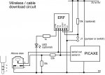
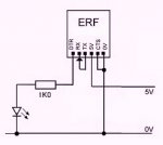
4) The DTR pin can supply an absolute maximum of 4mA to drive the optional activity LED.
Therefore an external 1k resistor is recommended in series with the LED. Drawing a
larger current may cause unreliable operation.
5) The CTS ‘chip enable’ pin has a ‘weak’ internal pull up resistor, and so the external 10k
pull-up is optional. However we recommend adding it to provide a ‘strong’ pull-up in the
circuit.
6) To use two or more URF/ERF pairs in close proximity (e.g. in a classroom for 2 remote
robots) each pair should be configured to use a different frequency via the URF
configuration wizard, which is a free download from www.picaxe.com/downloads/urf.zip.
The default frequency is 868.3MHz and this is the frequency the antenna is optimised for.
Other available frequencies that work well with the on-board chip antenna are 868, 915
and 903. However in a short range (e.g. 10m or so within a classroom) very different
frequencies such as 315 and 434 will also function, giving up to 6 default pair options.
 

pkf

Member
I did not connect CTS to anything. It was based on a previous recommendation that I didn't have to.
 

tarzan

Senior Member
I did not connect CTS to anything. It was based on a previous recommendation that I didn't have to.
You must connect/switch to ground CTS for programming to take place.
You should also add 10K pullup resistor to CTS.
Using the download socket puts your Tx & Rx connections on the wrong side of the download circuit.

In the picture I’ve added a 10K pulldown resistor to the ERF modules Rx line, this was needed to get reliable communications.

ERF.jpg
 

hippy

Ex-Staff (retired)
The MicroBot was not designed to have an ERF connected to it though it should be possible to do that and provide for wireless programming.

There are currently no proven recommendations for connecting an ERF to a MicroBot and we would suspect that no one has actually done that and proven it works. There will be suggestions as to how it can be achieved but with no guarantee that those suggestions will work. It may be necessary to modify suggestions in the light of results seen.

Miswiring the ERF may cause damage to the module. It is very difficult to say if this has occurred. If the ERF has been damaged it may be that it will not be possible to get it to work. But it not working does not necessarily mean the module is damaged.

We would recommend disconnecting the ERF from the MicroBot and wiring it so it is in loop-back mode. Connect 0V and V+ with CTS to 0V and RX connected to TX. The PICAXE Editor Terminal can then be used to check that what is sent to the ERF is received back which will confirm that it is working as expected and has not been fatally damaged.

We would also recommend getting the ERF to work with some other PICAXE chip using the recommended wiring configuration before trying to get it to work with a MicroBot. If the ERF does not work with that PICAXE it will not work with the MicroBot. If it works with the PICAXE then it should work with the MicroBot. This will help identify whether there is an underlying problem or simply a connection to MicroBot issue.

CTS needs to be connected to 0V for the ERF to be enabled. If CTS is left floating or pulled-up by the recommend but optional 10K it will be disabled.
 

pkf

Member
Hi tarzan, to be sure I didn't overlook anything what function does the circuit you have shown perform ?
Hi hippy, >>>Thanks<<<. I was aware that previous exchanges in another thread was not based strictly on a Microbot solution. I would have tried on the Microbot anyway if there was a possibility for it to work in principle, whether it actually does or not. For the suggestion to connect CTS to 0V and RX to TX, do we mean I can do this independent of any PICAXE chip for a start ? I don't have another PICAXE chip on hand, though it doesn't mean I cannot make plans to bundle it as part of the purchase with other items.
 

hippy

Ex-Staff (retired)
For the suggestion to connect CTS to 0V and RX to TX, do we mean I can do this independent of any PICAXE chip for a start ?
That is correct; the ERF loop-back configuration does not require a PICAXE. The LED+R on DTR is optional -
 

Attachments

Top