Audio VU noob problem

CDTMT

New Member
Hi everyone first post here and its a problem (as I am sure is often the case).

I have spent the last week building and programming a mini vu meter. I am using the 28x1 with output to 8 leds.
The design works beautifully and I was about to print up a PCB when I noticed a bug.
With the serial cable out the meter just slowly raises to the top where it stays.
As the cable is removed the pcaxe resets (not sure if this is normal).
If the cable is reattached the level slowly drops and the vu begins to work.
I have read that the serial cable can affect ADC inputs but the thread I was reading died before a solution was mentioned.

I have read the FAQ, the manual, and every semi related thread in the archive and cant find an answer.

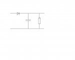
I've tried filtering out this affect through programming and had no luck. I have also tried putting a cap between the 0v and +V before it goes to the pic but this has no noticeable effect.

What is the serial cable doing to aide the circuit and how can I replicate it??

I am so sorry if this is a noob question that has been covered before but I am stumped.
 

Chavaquiah

Senior Member
This is mentioned in several places in the manuals and datasheets, but just to make sure: without the serial cable attached you must have the serial in pin tied to ground (use a pull-down resistor). Otherwise the pin will float, causing the Picaxe to reset. Could it be the problem here?

Oh, and nothing wrong with starting with a problem. We learn more from those, don't we? ;)
 

Dippy

Moderator
Best to post the schematic of your circuit.
If people here can't spot anything obvious then post the PCB artwork.
 

CDTMT

New Member
Hi, thanks for the quick responses.

I've just rechecked the download circuit. With the cable in serial in is connected direct to 0v. With it out its reading 24k, which seems wrong. To double check I grounded serial in which had no effect.

Just to clarify, its not the cable that allows the circuit to work, it must be connected to a pc.

pcb art work isnt finished, at the moment the chip is on a dev board made from strip-board and a small proto board. This is the first time I've used this so there could be a problem with it.

I can quickly draw up a schematic and a photograph of the dev board if that would help. I could also do the pcb art work now, but would rather leave that till I've fixed this problem incase I need to add more components to the design. Also the final design will be all smd, not sure if that makes a difference.
 

Dippy

Moderator
Always best to draw a schematic of what you are doing BEFORE making a circuit.
The more planning the less likely a cockup.

Yes, please post a schematic.
It's 99.999% that you have made a simple error that a second pair of eyes can spot in 10 seconds.
Don't make it a "quick" schematic, make it an "accurate" schematic ;)
 

CDTMT

New Member


I am fairly sure this accurate.

The reason for multiple resistors was just due to me not having the ones I needed. The leds are grounded by pin 12 so I can dim them as part of the animation.

Also I couldn't find an eagle lib for the pic 16f888 so I used the nearest I could find.

Just as a side note if anyone has an eagle lib for picaxes that would be a big help. I need the smd version.
 

Dippy

Moderator
"I am fairly sure there aren't any icebergs." - Captain of Titanic. ;)

I see one line for the audio_input connection. No Ground reference?

What is the audio source? Not ideal to feed an ADC with AC (i.e. +/- wrt Ground).

I thought WestAust and Mycroft have done a load of symbols/ artwork-footprints for Eagle?
Or was it Diptrace?
One of the cheap freebies anyway.
Why can't you do it yourself?
In my CAD it would take about 10 minutes.

PS. Sometimes resistor values aren't super crucial. E.G. The Reset pullup is fine at 10K.
 

MPep

Senior Member
The LEDs are shown with incorrect polarity.
Regarding the problem you have: suspect SerIn not grounded, OR an Earth link missing somewhere.
Eagle most certainly does have PICAXE chips in there. Downloaded mine about 3 years ago. You may have to search for them. Can't remember where I found them.

Regarding:
Not ideal to feed an ADC with AC
Your best bet is to rectify the signal, then feed the DC into the ADC.Use a diode and capacitor, with a resistor to bleed of the DC back to zero. This may require exeprimentation to get the correct attack/decay times.
 

CDTMT

New Member
"I am fairly sure there aren't any icebergs." - Captain of Titanic. ;)
RL lol

I see one line for the audio_input connection. No Ground reference?

What is the audio source? Not ideal to feed an ADC with AC (i.e. +/- wrt Ground).
Sorry I realize I am probably leaving out information. The audio source is a psp games console, the input is coming direct from one of the speakers. I have used this method for an analog (quad-opamps) vu meter in the past with now problem.

The speakers do have +/-. How do i use the ground refarence. Also why would it work without it while conected to a pc?

The psp is also the power sauce for the whole project.

I thought WestAust and Mycroft have done a load of symbols/ artwork-footprints for Eagle?
Or was it Diptrace?
One of the cheap freebies anyway.
Why can't you do it yourself?
In my CAD it would take about 10 minutes.
Yeah I can make them myself. I was just being lazy :(

PS. Sometimes resistor values aren't super crucial. E.G. The Reset pullup is fine at 10K.
Thats very usefull info, thanks. I thought I would need to buy more smd resistors for the final board. You just saved me a few quid :)


The LEDs are shown with incorrect polarity.
Oops. Sorry I am not used to having my schematics viewed by anyone. I hope its readable apart from that.

Regarding the problem you have: suspect SerIn not grounded, OR an Earth link missing somewhere.
I hope it is that. Apart from being a bit embarising.


Eagle most certainly does have PICAXE chips in there. Downloaded mine about 3 years ago. You may have to search for them. Can't remember where I found them.
Hmm. May be I was going about it wrong, I was looking for microchip pic's I didnt think of searching for picaxe. I'll have another look. Thanks for the suggestion.

Your best bet is to rectify the signal, then feed the DC into the ADC.Use a diode and capacitor, with a resistor to bleed of the DC back to zero. This may require exeprimentation to get the correct attack/decay times.
Ok. I thought the cap and resistor I was using was enough. I didn't think of using a diode. Not sure I am understanding you correctly, but I'll have an experiment.

Thanks again for the replys. Once the projects finished I'll post up some stuff.
 

Dippy

Moderator
If the PSP is the power source (only HP Hot&Spicey is a power sauce ;) )then you should have a ground.
If the speaker "-" is connected to that same ground then your speaker "+" is applying AC to the PICAXE ADC - not healthy and you were probably saved by the large value resistor. I had assumed audio line voltages, I don't know what the PSP chucks out - do you?

The PICAXE ADC measures POSITIVE voltages with respect to Ground. You are shoving in postive and negative by the sound of it.

The usual method is that suggested by MPep. The rectifying chops off half the wave, the capacitor acts like a reservoir and a bleeding resistor allows control of (among other things) the response.

As the ADC measures voltages bewtween 0V/Ground and +V (e.g. 5V if your PICAXE is supplied with 5V) then you must ensure that the rectified signal never goes above this. You may be able to combine a potential divider and a bleed resistor 'in one'.
This could require a lot of playing with values. With a 'scope you could do it in 5 minutes.

The original issue is probably a component or connection missing/faulty.
 

hippy

Ex-Staff (retired)
I'd suspect the speaker is driven through a bridge-style driver to get higher volume so neither - or + will be ground. Also there's no R's in series with the LED's.

Also the download jack plug is not wired correctly, nor is it shown how the mode switch is wired.
 
Last edited:

MPep

Senior Member
Ok. I thought the cap and resistor I was using was enough. I didn't think of using a diode. Not sure I am understanding you correctly, but I'll have an experiment.
See the attached circuit. This is how to wire it up. You may require a DC blocking capacitor, depends if the PSP audio output has DC, as well as AC of course (!), with respect to GND.
The value of capcitor and resistor are upto to you to experiment with.

[circuit drawn using MS Paint :)]
 

Attachments

Dippy

Moderator
I'd be tempted to expand that rectifier circuit if the PSP Amp is running at >3.3V.
1. Replace the single resistor with a pot/div and take that to the PICAXE ADC.
or,
2. Replace the resistor with a pot and take the wiper to the ADC. i.e. an adjustable pot/div.

This will ensure that ADC never sees more than 3.3V (assuming your PICAXE V+ = 3.3V).
These sorts of projects are hugely helped with a 'scope. Like I said before; 5 minutes.

As to whether any of the speaker terminals are Ground, 10 seconds with a DMM will find that.

I think you have a bit more reading-up and testing to do before CAD.
 

CDTMT

New Member
Thanks for the advice everyone. This is now working on the breadboard. I'll build a pcb today and test that.

The way I fixed it was to add a diode between the adc input and 0v (this being the main ground of the psp and not that of the speaker).

I am not sure if this is how it is supposed to work. But it is working.

Is there any reason that I shouldn't use this method? Could I be damaging the pic in any way?

I am testing it now and will leave it running for the next few hours.
 

hippy

Ex-Staff (retired)
Is there any reason that I shouldn't use this method? Could I be damaging the pic in any way?
It would be good to see your circuit diagram for exactly what you have now in order to comment on it.

PS : It's a "PICAXE", not a "pic".
 

CDTMT

New Member
Hi hippy. here you go.


the mode select button is wired to a trace on the psp motherboard which is connected to one of the function keys so as to be fully integrated. this works without problem.

I realize now that the download plug is not shown as being wired correctly, i am still getting used to eagle.

the leds are operating without any resistors. I wanted to keep the part count low as there is little space in the psp for a large pcb. Its seems to work without issue.

As a side bonus. since adding the diode the vu is a lot more responsive, particularly when the volume is low. Also I did not have to change any of the adc values in the code.

*please try to ignore spelling irregularity. Its due to me relying on firefox spell check. I use that because doctors claim I have dyslexia. While I maintain that its due to poor education/laziness.
 

hippy

Ex-Staff (retired)
Operating the LED's without resistors is likely to damage the PICAXE and possibly overload the circuit (damage the PSP if that's what's powering it ). That becomes more likely the more LED's are on and the longer they are on for. They can be pulsed / multiplexed to be driven with resistors rather than turned on and left on but it's not recommended practice.
 

BeanieBots

Moderator
I'll second Hippy's comments about the LEDs. A disaster waiting to happen.
Your diode is correct but make sure it is a schottky type.
The 600k feeding the input is too high for reliable operation of the ADC.
I don't know what your source voltage is but you should reduce the input impedance to around 10k. That may well require designing a potential divider for the input.

Also, don't lose too much sleep about getting the exact value for MCLR pull-up. 2k2 will be fine if that's all you've got.
 

CDTMT

New Member
Thanks again. Will add resistors now. I'd like to use very low values for them as they are not especially bright. Would 50r be ok on the neg side? This way I would only need to add one more component to the design, or must they have individual resistors.

Also, don't lose too much sleep about getting the exact value for MCLR pull-up. 2k2 will be fine if that's all you've got.
how about on the download circuit?
 
Last edited:

Dippy

Moderator
I'll third that.
You are probably saved by the fact that most LEDs are going on and off.
However, there will come a time...
You can get SIL networked resistors which are very thin. Probably cost 50p which is cheaper than a new PICAXE.


But if you are happy with it then so be it.
 

BeanieBots

Moderator
Download circuit is not very critical either.
15k to 33k should be fine. Lower (1k) if your serial is 5v or if you are using the AXE027 download cable.
 

inglewoodpete

Senior Member
As mentioned by someone else previously, the wiring for the programming socket is drawn wrong for the AXE026 or AXE027 programming leads (in both versions of the drawing to date).
 
Last edited:
Top