Audio Signals

George Sephton

Senior Member
Hi All,
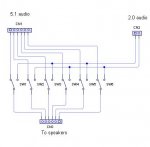
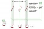
im having some trouble with a project I'm making, it's basically an AV selector, 4 x Audio and Video in, 1 x Audio in and 1 x PC Audio in (5.1 green, orange and black). The signals are selected using MAX 4614 and a decade counter and ultimately end up into 4 channels, Left, Right and Video and Ground. But these excludes PC audio which ends up as 9 channels, L,R and GND for Green, Orange and Black. However at the last moment I need to combine these 2 so they can be outputted to a set of 5.1 PC Speakers (again green, orange and black).

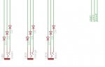
I've done the entire circuit and reached what's in the picture. Now I need to combine those 2 outputs, However: The PC output needs to keep the orange, green and black seperate but the other outputs need to share the outputs so L goes to orange, green and black L etc. How can I do this without the signals going to different outputs when PC is selected.

Sorry this is really hard to explain but I know it requires some sort of diode arrangement, Im just not sure what.
Thanks for any help,
George.
 

Attachments

Dippy

Moderator
"Sorry this is really hard to explain"
- and even harder to understand :)

"I've done the entire circuit and reached what's in the picture"
- there must be more to it than this.


Best you draw up and post the complete circuit as you have it.
Because I can't understand what you are talking about.
Are these AC signals? And you have diodes?

You know you can easily mix AC signals using op-amps?

I hope BB can shed some light ??
 
Last edited:

BeanieBots

Moderator
I've done the entire circuit and reached what's in the picture.
Please post the entire circuit and not just what's in the picture because I can't follow what you are trying to do either.

As this is 5.1 and only three wires and using diodes I assume it's digital data??

EDIT:
Sorry Dippy, my xtal balls aren't working either!
 
Last edited:

Andrew Cowan

Senior Member
As far as I understand, he has 6 speakers.

When connected to a standard audio source (eg am MP3 player), he want to split them into two sets - right channel and left channel.

When connected to a PC, he wants to use each individually, as is possible using a 5.1 channel soundcard.

Therefore, he wants to switch between one setup where half the speakers are connected to each other, and another where all speakers are disconnected. Am I close?

George - neither of you circuit diagrams will work - as Dippy points out, remeber audio is AC, not DC. Can you make do with a manual switch or relays?

A
 
Last edited:

hippy

Ex-Staff (retired)
There is presumable a set of 6 speakers for 5.1 reproduction, thus six outputs in total. The six selectors ( one per output ) will select what goes to each of the outputs; 'straight through' when selecting the 5.1 source, the inputs feeding multiple outputs when selecting a mono or stereo source.

This should be no more difficult or complicated than having a six-pole manual switch to select routing ( 12 pole if lines to speakers are switched rather than audio signals that feed to amplified speakers ), the digitial multiplexes replacing each pole of the switch.
 

George Sephton

Senior Member
Andrew is right, there are 3 wires as that is 5.1 surround sound from a computer's soundcard. 3 are 3 3.5mm jacks. Green being Front L and R and Orange and Black being Rear L and R and Centre and Bass ( I forget which is which )
I currently have one of these to deal with my audio problem:
http://www.logitech.com/lang/images/0/12087.jpg

But I have a lot of audio inputs and before I was using phono splitters on the end of this but this causes noise :( so now Im creating a splitter.

To explain the schematic, please note that it all works. I've had a MAX4614 in a breadboard with both an Audio and Video signal going through it and they can be turned on and off easily.

In the circuit I have all the inputs come in, then go through a MAX4614 to determine which is on (the decade counter ensures only 1 is on at a time). these then come out into the output channels. Video is fine as that can go straight to a RCA Connector.

The Audio out is the problem. The output for audio will be 3x3.5mm jacks for my 5.1 speaker input. 2.0 just needs left to go to all 3 left jacks and right to go to all 3 right jacks. and then the 1 pc input to go to straight to the same connectors. However if I connect all the 2.0 to the 3 jacks this will allow the 5.1 output (when selected) to go to other channels and is left with a 2.0 output. This is why I was thinking diodes, however I didn't realise diodes don't work with AC.

P.S Does anyone know which is rear and sub of the orange and black connections because I can't remember or find it anywhere.
 

Attachments

Andrew Cowan

Senior Member
Orange is sub/centre, but which is which can vary depending on make/model

I'd just use a SPDT switch per speaker (so three DPDT switches in total). For the switches, you could either use relays, or analogue parts (eg the 4066).

The switch would switch between the 5.1 connection and the 2.0 connection.

A
 

George Sephton

Senior Member
Im using MAX4614 because I know they work and they're cheaper than relays. But you think I should just use a switch after the 5.1 output and the 2.0 output and then have the 5.1 go straight through and the 2.0 combine....
But wait the 2.0 will have to convert to 5.1 at some point and when it does It'll connect different lines, like the green L, orange L and black L will now all be connected and make the original 5.1, 2.0.

How can I combine the audio signals here without ruining the setup of the 5.1?
 

George Sephton

Senior Member
Ah ok,
that makes a lot of sense.
Just one thing I didn't realise before. For the orange connector (centre and bass) I don't want L to L and R to R otherwise I'll end up with centre being L and bass being R, so I need to combine L and R for both Centre and Bass.
 

Andrew Cowan

Senior Member
You don't like making things easy, do you :)!

I'd use an op-amp to mix the two signals - with a dual supply, it'll be fine with AC.

A
 

hippy

Ex-Staff (retired)
If the speakers are not directly driven from a single input source, need to be driven by a combination of input source ( eg, mixing left and right of a stereo signal to produce a bass signal ) you will have to mix those two signals together then select that mixed signal into your switch / multiplexor.

Such a mixer would normally be created using an op-amp.

The first design for a simple mixer I found on Google is at the bootom of the following link. There are many other variations using a variety of op-amps.

http://www.all-electric.com/schematic/simp_mix.htm
 
Top