Audio PCB HUM!!!

George Sephton

Senior Member
Hi all,
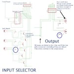
I've had a PCB fabricated and one of the features on the board is an audio input selector. This works with a PICAXE connected to a decade counter which counts to the correct input. Each input (a 3.5mm audio connector) has L, R and GND which comes out and joins to 3 lines, L, R and GND, but with a transistor between the Jack and the line, except for GND which are all linked together. So when each number on the decade counter is selected, 2 transistors for the appropriate input open allowing the audio onto the line. This line then goes to a jumper (to a seperate digital potentiometer, not connected for my problem) and returns where it goes to 2 phono connectors, I have attached the schematic with annotations to explain this.

Now when I select and input, the sound that returns is always a loud hum, often with a slight rhythm of the song on my ipod in the background, or sometimes returns a sound like a galloping horse.

Please help me with this problem, it doesn't make any sense. I have used a little speaker with wires attached to see if audio can be heard throughout the pcb, I know for a fact the audio is coming in fine from the socket.

I have just looked at the transistors (SOT-23 SMD) and the sound works on the collector and GND but the emitter and GND emits a hum, so I'm assuming there must be something wrong with these?

Any help would be appreciated so much,
George S.
 

Attachments

Last edited:

hippy

Ex-Staff (retired)
Can transistors be used in that way as audio switches ? I thought the innards of a transistor were effectively diodes but transistor theory isn't my forte. Most audio switchers I've seen use FETs ( of some sort ) or 4016 switch IC's.
 

MartinM57

Moderator
Oh dear. If your circuit is anything like the schematic indicates, I'm afraid this will fail big time :(

...if it's not already blown all the transistors up when the +5v output from the decade counters has been directly applied to the bases with the emitters connected to ground.

You can't use 'ordinary' transistors as analogue switches just by setting the base to +5v and connecting what you want across the collector-emitter.

As Hippy says, 4016 analogue switches are the sort of thing you need...
 

Buzby

Senior Member
I agree with hippy, I've never seen normal npn or pnp transistors used as analogue switches. I would be very surprised to see them do anything relating to analogue without some kind of biasing.

One way might be to use them in a 'normal' way, signal into the base and out at the collector, but with a common load resistor. Then pulling all but one base low would allow the remaining signal through.

Did you breadboard this before having a PCB made ?

Edit : 4016 or 4066 ?. I think the 4066 is designed for analogue, if my memory goes back that far !
 
Last edited:

BeanieBots

Moderator
As others have already stated, you simply can't use a transistor that way!
The 4066 would be your simplest option but if you have time and patience and are prepared to do a lot of transistor theory, then it is possible to use a fairly simple circuit based around a dual pair of FET transistors to vary the impedance of a line which when combined with a load will give a very similar function to an analogue switch.

As for your hum, that will be caused by having high impedance lines on your circuit board that are picking up radiated mains frequency from nearby wiring.
There are several ways to reduce it.
Firstly, good shielding. Use of co-axial cable when linking off board and guard traces either side of the signal track when on PCB. Ideally, you should also have two seperate layers for shielding but that can make the PCB very expensive.
Keep impedances on all audio tracks low.

Also, make sure nothing from your power supply is coupled to your audio lines. Again, guard traces can be very good at eliminating supply coupling but it is better to decouple the supply itself rather than to try and eliminate its effect on your circuit. If you take the option of using an analogue switch such as the 4066, make sure it is properly decoupled and that there is plenty of 'headroom' between the signal and either power rail voltage or you will get clipping. The best way of doing this is to AC couple the signal onto a mid point DC offset.

Don't forget, even devices like the 4066 are not perfect. They will present problems such as "cross talk" where the signal 'leaks' from one channel to another, and "bleed" where the switch is not completely off. These effects can be reduced by applying appropriate impedance matching between your channels.

Alternatively, just use reed relays to do the analogue switching.
The methods to reduce hum still apply though.
 

Dippy

Moderator
George, a transistor cannot always be thought of as a solid-state relay.
There is far more to switching analogue signals than chucking a tranny at it.
I haven't studied your 'circuit' but I expect you've got all sorts of mixes and half-signals and whatevers.

You have learnt 4 lessons here:
1. A lot more time at electronics school is required.
2. Breadboard is useful - especially for the novice.
3. Walk before trying to run.
4. Get books and articles and read them. If you get stuck ask your teacher.
 

vttom

Senior Member
Here's a thought that might get your existing project board to work...

Install your transistors with the collector and base connections swapped.

What you'll wind up with is an emitter-follower on each analog channel. When you pull the collector high, the transistor will conduct and the emitter will "follow" the voltage at the base (minus a threshold voltage). When you pull the collector low, the collector-to-emitter voltage will = 0, causing the transistor to stop conducting.

But this is just a "quick-fix" idea. It is far from a complete revision of the design. It's missing all sorts of considerations of DC biasing, AC coupling, etc. which are good design practice when interfacing with audio gear.
 

Buzby

Senior Member
Let's not be too hard on George.

He has put a lot of work into designing and building his circuit. He knows exactly what he wants it to do, which always aids us who are trying to help.

Unfortunately he had a limited understanding of the actions of a transistor.

This I can understand this. In this 'digital world' the transistor is always treated as a switch. Even the PICaxe manual talks about transistors switching.

Extrapolating from switching a lamp to switching an audio signal is not so ridiculous, if you have only been taught that a transistor is a switch.

The only thing I would say to George is breadboard ideas first, before committing to PCB.

( We all learn from our mistakes. I remember my early transistor circuits. I wired two OC71's together, leg-to-leg, and expected to get twice the volume out of my loudspeaker. There was no internet then to tell me why it didn't work !.)

George, don't stop learning !.
 

Andrew Cowan

Senior Member
The 4066 has a bit of resistance - about 60 ohms if I remember correctly.

Maxim have lots of similar types with lower resistances.

A
 

BeanieBots

Moderator
Absolutley AC, they are NOT perfect switches by any stretch of the imagination. That's why even in todays day of almost a chip for any app, much precision analogue work still uses relays. Horses for courses and all that.
 

George Sephton

Senior Member
Hi all, thanks very much for everyone's feedback, certainly I have learned a little bit more about transistors, and they really aren't as simple as I expected. I was just wondering firstly if I connected USB signals in the same way would that work? and also would this (http://www.maxim-ic.com/quick_view2.cfm/qv_pk/2071/t/al) be a good a replacement for the 4066 ic, and would it work? Obviously I'll test this in a breadboard first :S
Thanks so much,
George S.
 

BeanieBots

Moderator
I was just wondering firstly if I connected USB signals in the same way would that work? .
Connect what USB signals in what way with what expected result?

The analogue switch you link to has a better overall spec than the 4066, but if it is suitable for any specific application depends on the app.
For example, it has a resistance of ~10ohm so it would be fine for switching line signals into an amplifier, it would just about cope with signals to a set of low power headphones but it couldn't switch signals to a speaker.

You are still lacking the absolute basics to be getting involved with more complex issues such as signal switching.
Read up on the basics. Ohm's Law would be a good starting point.
You'll never understand anything electronic without it.

We're here to help but you are floundering because you have missed some fundamentals right at the beginning. Walk before you run.

Transistors ARE simple. That's the problem, they are TOO simple for what you want to do.
They are current amplifiers.
The current flowing from base to emmiter (for a NPN type) will allow a current of hfe (a value for the transistor you can get from the datasheet) times that current to flow from the collector to the emmiter. THAT's IT. ALL OF IT. There really isn't anything else of significance to know. (well.. not just yet anyway!).
 
Last edited:

MartinM57

Moderator
(not that I really understand what this circuit is trying to do - is it some sort of sequential audio multiplexer? With maybe something clever going on in the digital pot area to equalise the volume of the channels? And if there's a PICAXE in the mix, then why the rather old fashioned decade counter that you are only using 3 outputs of - couldn't a suitable PICAXE do that bit as well? EDIT:.. and the decoder counts from 0 to 6 then resets, so over half the time no audio channel is switched 'on', but the (off-schematic) LEDs light up?)

Have never used the 4066/4166/4610/4614 etc etc switches so have just spent a few mins looking at the data sheets. I see (at least) 2 possible gotchas that might getcha if you didn't read and appreciate them carefully:

- "Each switch handles V+ to GND analog signal levels" - so don't go thinking you can just connect V+ (as +5v) and Gnd (as 0v or earth) and expect them to pass audio, which is inherently AC (i.e. has negative voltage components). If you look carefully at the application circuits for audio switching you will see that +ve and -ve supply voltages are used, which is an extra complexity that would be needed by your circuit

- "Proper power-supply sequencing is recommended ... Always apply V+ before applying analog (sic) signals or logic inputs, especially if the analog or logic signals are not current limited" - so if you have audio present on the input to the switches, but your unit isn't powered up, you need extra components as detailed in the data sheet.

So even using these devices as audio analogue switches is non-trivial....looks like some miniature old-fashioned relays would be the best thing....
 
Last edited:

George Sephton

Senior Member
I did know about the resistance and these are line level signals which is why i'm not worried about it. To explain it basically, it is an audio input selector (with loads of other stuff attached, hence why there's a picaxe, not just a button) so the input is selected and then sent to an output. As for the USB thing, I have a USB input (from an iPod) and between the ipod breakout and the USB plug are the D+ and D- lines which have 2 transistors between them so they can be enabled at any time (ie to control when the ipod syncs and just charges). Can a transistor be used for USB signals? and also would the 10 ohms on my MAX4615 affect the USB signals or not?
George.
 

Andrew Cowan

Senior Member
Can a transistor be used for USB signals?

Probably not - have you scoped the USB signals?

and also would the 10 ohms on my MAX4615 affect the USB signals or not?


There's only one way to find out for sure!

A
 

MartinM57

Moderator
Can a transistor be used for USB signals? and also would the 10 ohms on my MAX4615 affect the USB signals or not?
Hi George

I'm sure you can Google "switching usb signals" as well as anyone else .... and it quickly turns up a tutorial at http://www.analog.com/library/analogDialogue/archives/40-01/usb_switch.html that shows, if you believe everything you read on t'Internet, that:
- it's not as simple as it might initially seem, especially for USB2
- a transistor is not going to work
- the 10 ohms resistance of a MAX4615 is probably bad news
- be very careful with PCB layout.
 
Top