Thanks for your help guys. I've pasted in below my emails to and from MAXIM. As you guys have already stated it appears the problem is the inductor is saturating.
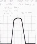
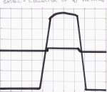
Ive got a old glass screen scope and so I cant get a screen shot of it.
The device charges the battery OK and terminates fast charge and goes to trickle charge OK. It does not appear to be heating the coil on trickle. Of course it could still be misfunctioning on trickle I suppose but with the small current flow (100 milliamps it cant generate any heat).
So I was thinking to look at the coil wave form when the device is trickle charging and then compare that with how it looks on fats charge when it is over heating or running hot and, presumably, saturating.
What differences am I looking for? When saturated and not longer switching I suppose the coil wave form will be a flat line? where as when its working OK I should see a square wave?
Where do I measure the coil wave form from?
I am using the exact diodes specified in the data sheet MBRS340T3.
Regards,
Brendan.
Hi Brenden,
This is regarding our recent conversation on the MAX713. Up on further investigation, it looks like the part numbers you gave me for the MOSFET and inductor should be adequate for your application without significant heating. I suspect the excessive heating may be due to parasitic inductance causing more than expected voltage levels in your circuit. Please send me the schematic and layout of your board for further investigation. Also, if possible please measure the voltage across and current through the MOSFET and inductor using an oscilloscope and let me know what you observe.
Regards,
Ben Wolde
MTS Customer Applications Engineering
Maxim Integrated Products, Inc.
120 San Gabriel Dr. MS 165
Sunnyvale, CA 94086
New email:
ben.wolde@maxim-ic.com
Hi Ben,
Thanks for your help. Im under the pump with this thing, I originally wanted to use the MAX712 but couldn't because of heat dissipation problems.
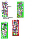
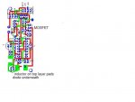
I have attached a jpeg scan of a print out of the pcb design. My pcb program wont let me export a pdf it seems. Ive emailed them and if they get back to me I'll send on a color view. Which will make things clearer.
There are four views depicted.
Top left is tracks only.
Top right shows both top and bottom layers.
Bottom left is component layer only.
Bottom right is copper layer only.
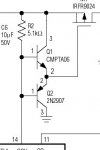
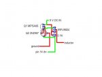
I drew the pcb according to the schematic depicted on the in fig 19 page 16 of the MAX712-MAX713 data sheet. I am using a R25 as a current sense R. (R3)
There are couple of misreprensentations in the print out. I use a MPSA06 in a TO-92 package in place of the CMPTA06.(Q1 on the schematic) The print out shows the MPSA06 the wrong way around, I have the part the correct way around on the board.
The 10uf electrolytic on the bottom left of the board (C3 on the schematic) is shown polarity reversed. This is corrected on the pcb.
The battery pack I'm testing with is composed of three 3700 Gold Peak mAh NiMH batteries in series.
I took the following readings:
With DC in being 9V:
There is 1.15 amps going into the battery on fast charge
49 milliamps on trickle
charge terminates when cell pack reaches 4.7V
MOSFET
gate 3.19V
drain 5.59V
source 8.99V
MAX713 pin levels are as follows during fast charge:
Vlimit 2.28V
Batt+ 5.22V
PGM0 5.22V
PGM1 2.27V
THI 5.22V
TLO .6V
TEMP .77V
(fast charge indicator is operating correctly, I have a LED hooked up to it via a 470R and it lights when fast charging and goes out on trickle)
PGM2 2.27V
PGM3 2.27V
CC 2.29V
BATT- .28V
DRV 3.55 V
V+ 5.22V
REF 2.28V
I hope that information gives you some insight into what is going on. My brain is fried for today, Ive got some mcu programming to do so Ill 'relax' doing that and come back to this in the morning
Regards,
Brendan
i Brendan,
Thanks for sending the information. I am having trouble identifying components on your layout picture. Please let me know where the inductor and MOSFET are located. Also, I need to see the actual scope shot showing the current through the inductor and the voltage at the node where the MOSFET and inductor connect. That way we'll know if the inductor is saturating and what value inductor to replace it with.
Regards,
Ben Wolde
")