There was a thread here a few weeks back regarding anemometer efficiencies. That is, you calculate the revolutions per time for a particular wind speed but for various reasons you are unlikely to get that relationship in the real world. I just completed and calibrated my 3-cone cup anemometer that has a 3 inch radius to the center of the cup. My calculations indicated that 1 mph would be 0.93 revolutions per sec. I calibrated it by sticking it up through the sunroof of a truck such that it was 4 to 5 feet above the roof, used a GPS to indicate speed, and calibrated it in 5 mph increments for 10 sec periods using 4 averaged readings per speed. I was pleasantly surprised to find a tight linear relationship from 5 to 50 mph (speed (mph) = 0.296 (count per 10 sec) + 4, with r2 ~ .85). Calculations for 50 mph indicated 47 rev/sec but reality was 16 revs/sec giving an efficiency at 50 mph of 34%. I don't have proper bearings, the cups are mounted on a brass rod that is sharpened to a point at the bottom which rests on a bit of metal inside a brass tube that is about twice the diameter of the rod. The upper end of the rod is supported by passing through a hole (1/64 inch larger than the rod) in a PVC pipe end cap so there's certainly some slop in the system but it turns readily with little effort so I believe that the majority of the inefficiency is due to aerodynamic issues. The slop in the system really only becomes apparent at 50 mph but since we get 50 + mph winds here several times a year I think I'll start looking for some proper bearings.
anemometer efficiency
- Thread starter KIGX
- Start date
Thanks for the test results. I've been struggling for some time for finding a formula for for the cup anemometer tip speed ratio. I was pretty certain before, that it would be in the range of 0.65-0.8, but this proves otherwise.
I think I'm going to have to make a similar calibration to my anemometer, before sticking it up to the windmill tower.
I think I'm going to have to make a similar calibration to my anemometer, before sticking it up to the windmill tower.
Peter M
Senior Member
bearings
KIGX - a good range of bearings can be had at your local hobby shop.
In particular model helicopters are full of nice little ball bearings.
(dare I say it?) These can be found on ebay too.
Like these. http://cgi.ebay.com/Esky-Lama-V4-RC-Heli-Parts-EK1-0328-Bearing-4-8-4mm_W0QQitemZ310137408639QQcmdZViewItemQQptZRadio_Control_Parts_Accessories?hash=item4835a14c7f&_trksid=p3286.m20.l1116
Nice data by the way.
Could you give any details about the size a shape of the cups, or even a photogragh?
krypton_john
Senior Member
Hi,There was a thread here a few weeks back regarding anemometer efficiencies. That is, you calculate the revolutions per time for a particular wind speed but for various reasons you are unlikely to get that relationship in the real world. I just completed and calibrated my 3-cone cup anemometer that has a 3 inch radius to the center of the cup. My calculations indicated that 1 mph would be 0.93 revolutions per sec. I calibrated it by sticking it up through the sunroof of a truck such that it was 4 to 5 feet above the roof, used a GPS to indicate speed, and calibrated it in 5 mph increments for 10 sec periods using 4 averaged readings per speed. I was pleasantly surprised to find a tight linear relationship from 5 to 50 mph (speed (mph) = 0.296 (count per 10 sec) + 4, with r2 ~ .85). Calculations for 50 mph indicated 47 rev/sec but reality was 16 revs/sec giving an efficiency at 50 mph of 34%. I don't have proper bearings, the cups are mounted on a brass rod that is sharpened to a point at the bottom which rests on a bit of metal inside a brass tube that is about twice the diameter of the rod. The upper end of the rod is supported by passing through a hole (1/64 inch larger than the rod) in a PVC pipe end cap so there's certainly some slop in the system but it turns readily with little effort so I believe that the majority of the inefficiency is due to aerodynamic issues. The slop in the system really only becomes apparent at 50 mph but since we get 50 + mph winds here several times a year I think I'll start looking for some proper bearings.
I would not expect much better from this style of anemometer as while the wind is blowing the open side of the cup away, a component of the other cups' surface area on the other side is pushing back into the wind. at a higher relative speed to boot.
I like the idea of an ultrasonic anemometer where an arrangement of 3 ultrasonic transponders ping each other and the airspeed is triangulated from the difference in propagation times. Would be interesting to see if a PICAXE was up to it.
= 3.125 mph/HzCalculations for 50 mph indicated 47 rev/sec but reality was 16 revs/sec giving an efficiency at 50 mph of 34%.
Just as a point of reference, the Davis weather station anemometer is a 3 cup, 4.75 inch diameter, single reed unit and its spec is 2.25 mph/Hz.
Rickharris
Senior Member
Even easier use a hot wire and measure the change in resistance as it is cooled by the wind. Should be well within a Picaxe + op amp.
I've never looked into that method Rick and I like the concept, so these are kiddy-level questions:
1. How do you compensate for ambient air temp?
2. Do you have to compensate for humidity?
3. Does it need an umbrella? (For sun and rain?)
4. How much power does it take c/w cup style thing?
5. Is there special wire for this?
6. Is it really 'easier' to get it working well?
1. How do you compensate for ambient air temp?
2. Do you have to compensate for humidity?
3. Does it need an umbrella? (For sun and rain?)
4. How much power does it take c/w cup style thing?
5. Is there special wire for this?
6. Is it really 'easier' to get it working well?
@Dippy
Compensation should be easy. Just tap the (Nichrome) wire in the centre, like a voltage divider, and conceal the bottom leg inside the housing or a tube, shaded from the moving air.
Wheatstone bridge measurements can then give you the resistance difference between the legs and hence the cooling effect of the wind on the upper leg and hence the wind speed.
The power used will depend on how small your measurements can be, and still give useful resolution.
And the best bit... No moving parts")
Compensation should be easy. Just tap the (Nichrome) wire in the centre, like a voltage divider, and conceal the bottom leg inside the housing or a tube, shaded from the moving air.
Wheatstone bridge measurements can then give you the resistance difference between the legs and hence the cooling effect of the wind on the upper leg and hence the wind speed.
The power used will depend on how small your measurements can be, and still give useful resolution.
And the best bit... No moving parts
Rickharris
Senior Member
Boritz says it all - This is how many commercial systems work so I guess it's cheaper.
On an off the wall idea perhaps you could use the shape memory wire and connect to a mechanical pointer - as the air flow cools the wire the pointer moves!
On an off the wall idea perhaps you could use the shape memory wire and connect to a mechanical pointer - as the air flow cools the wire the pointer moves!
Jeremy Leach
Senior Member
I dabbled with a cup anemometer using reed switch to count revs and it seemed a good low power solution. However the downsides I felt at the time were:
- Mechanically quite tricky to construct a nice 3 cup anemometer.
- A low friction bearing is really needed for repeatable results.
I like the idea of a generator idea (discussed before), where a simple motor acts as a generator - bearing taken care of. Also I like the idea of somehow tapping off the generator to top up rechargeable batteries that power the picaxe circuit ! Haven't seen this done before and not sure how difficult it would be - because it would be like having a varible load on the generator and so it might not be easy to actually measure the windspeed ???
A cup type anemometer is essentially a Vertical Axis Wind Turbine, and can be designed as a Savonius type
easily. This would provide more power for the generator.
The problem of effecting the speed by loading can be eliminated by only measuring the speed (say) one-in-five seconds, so that for the other four seconds, power is being delivered to the rechargables. It could be made completely wireless and self powering.
Jeremy Leach
Senior Member
Good thinking Boriz.
Also, just for interest, I've noticed Forrest Mim's circuit scrapbooks are now on googlebooks. Very old by today's standards, but classic experimenter stuff... and there is a little windspeed discussion on page 133 of Volume1 (Red book).
http://books.google.co.uk/books?id=-sE7JVywygQC&lpg=PP1&dq=accurate%201%20hz%20&pg=PP1
http://books.google.co.uk/books?id=STzitya5iwgC&printsec=frontcover&dq=accurate+1+hz+
EDIT: Sorry, they've removed those particular pages !!! I just happen to have the real book It's only pretty basic stuff though.
Also, just for interest, I've noticed Forrest Mim's circuit scrapbooks are now on googlebooks. Very old by today's standards, but classic experimenter stuff... and there is a little windspeed discussion on page 133 of Volume1 (Red book).
http://books.google.co.uk/books?id=-sE7JVywygQC&lpg=PP1&dq=accurate%201%20hz%20&pg=PP1
http://books.google.co.uk/books?id=STzitya5iwgC&printsec=frontcover&dq=accurate+1+hz+
EDIT: Sorry, they've removed those particular pages !!! I just happen to have the real book
It's only pretty basic stuff though.
Last edited:
Mycroft2152
Senior Member
Jeremy,
Those books are real gems.
There's a wealth of useful info in the "old" books by Forrest Mims (Circuit Scrapbook) and Don Lancaster (the CMOS Cookbook). Not to mention the old Radio Shack series written by Forrest Mims.
You may be able to find some of these in a used bookshop.
Myc
Those books are real gems.
There's a wealth of useful info in the "old" books by Forrest Mims (Circuit Scrapbook) and Don Lancaster (the CMOS Cookbook). Not to mention the old Radio Shack series written by Forrest Mims.
You may be able to find some of these in a used bookshop.
Myc
Thanks to all for all the comments. I'm pleased to have stirred up more discussion, you've given me a few more things to look into.
Peter M - thanks for the tip on the helicopter bearing, I'll definitely look into that.
My opinion is that the efficiency of an anemometer and its rate of rotation are highly dependant on how it's made - friction, stiction, radius, cup size and shape, etc. I am no aeronautical engineer so I just made something that looked right to me. First let me give a big nod to Jeremy Leach. Jeremy has a web site where he published all of his work on his weather station. I unabashedly stole some basic concepts from Jeremy but then proceeded to build and code everything on my own and I must say having a 28X2 available probably made some of it a lot easier.
Pictures hopefully attached below.
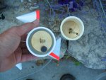
The cups are made of fibreglass/polyester and are about 2.5" (65.65mm) in diameter at the mouth and 3 5/16" (83.9mm) long. I made a wooden cone on a lathe (I do woodworking / woodturning) to get a cone that 'looked' right, coated it in beeswax, slopped on polyester resin, fibreglass mat, more polyester resin, let it harden, sanded it on the lathe and then repeated it to get 2 layers of fibreglass. The cross brace is 1/8" (3.17mm) plywood cut into a circle on the lathe, cut out to give the brace, and the ends angled to match the cup angle. The cups were glued to the brace with thick cyanoacrylate glue and then the joint was fibreglassed. (Jeremy made cups out of paper and varnish, which I thought was brilliant).
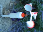
The body is a 2" pvc plumbing pipe with an end cap. The orange thing on the top is from a squeeze bottle of honey and the a 1/2" copper pipe end cap covers that to keep the rain out. Inside are disks, turned on a lathe and fitted.
Actually, the part of this that gave me fits was debouncing the magnetic reed switch. I read numerous places that switches bounce for 10 to 20 millisec. But, using theoretical calculations, at 50 mph (a goal I had set for myself) 1 revolution is 21 millisec so to debounce it would use up the entire time so that was not going to work. Playing around I found that I could use an RC network (discharges a .1uf cap thru 1K ohms and charges thru 4.7K+1K ohms) that debounced for a theoretical 160 microsec with recharge of 916microsec which uses very little time up. The switch is closed for 70 degrees of rotation, 4 millisec at 50mph in theory. Without the network the switch gives from 1 to 3 counts per rotation but with the network I have only seen 1 count per pass. Are reed switches particularly good for not bouncing? Also, I hooked this up to a Schmitt trigger pin on the PICAXE so that the 'slow' rise and fall between high and low wouldn't mess up the PICAXE.
I may need practice loading pictures so if they are not attached I'll try again.
Edit: see a couple posts below for another picture. I'll have to work on posting pics...
Peter M - thanks for the tip on the helicopter bearing, I'll definitely look into that.
My opinion is that the efficiency of an anemometer and its rate of rotation are highly dependant on how it's made - friction, stiction, radius, cup size and shape, etc. I am no aeronautical engineer so I just made something that looked right to me. First let me give a big nod to Jeremy Leach. Jeremy has a web site where he published all of his work on his weather station. I unabashedly stole some basic concepts from Jeremy but then proceeded to build and code everything on my own and I must say having a 28X2 available probably made some of it a lot easier.
Pictures hopefully attached below.
The cups are made of fibreglass/polyester and are about 2.5" (65.65mm) in diameter at the mouth and 3 5/16" (83.9mm) long. I made a wooden cone on a lathe (I do woodworking / woodturning) to get a cone that 'looked' right, coated it in beeswax, slopped on polyester resin, fibreglass mat, more polyester resin, let it harden, sanded it on the lathe and then repeated it to get 2 layers of fibreglass. The cross brace is 1/8" (3.17mm) plywood cut into a circle on the lathe, cut out to give the brace, and the ends angled to match the cup angle. The cups were glued to the brace with thick cyanoacrylate glue and then the joint was fibreglassed. (Jeremy made cups out of paper and varnish, which I thought was brilliant).
The body is a 2" pvc plumbing pipe with an end cap. The orange thing on the top is from a squeeze bottle of honey and the a 1/2" copper pipe end cap covers that to keep the rain out. Inside are disks, turned on a lathe and fitted.
Actually, the part of this that gave me fits was debouncing the magnetic reed switch. I read numerous places that switches bounce for 10 to 20 millisec. But, using theoretical calculations, at 50 mph (a goal I had set for myself) 1 revolution is 21 millisec so to debounce it would use up the entire time so that was not going to work. Playing around I found that I could use an RC network (discharges a .1uf cap thru 1K ohms and charges thru 4.7K+1K ohms) that debounced for a theoretical 160 microsec with recharge of 916microsec which uses very little time up. The switch is closed for 70 degrees of rotation, 4 millisec at 50mph in theory. Without the network the switch gives from 1 to 3 counts per rotation but with the network I have only seen 1 count per pass. Are reed switches particularly good for not bouncing? Also, I hooked this up to a Schmitt trigger pin on the PICAXE so that the 'slow' rise and fall between high and low wouldn't mess up the PICAXE.
I may need practice loading pictures so if they are not attached I'll try again.
Edit: see a couple posts below for another picture. I'll have to work on posting pics...
Attachments
-
 729.9 KB Views: 44
Last edited:
premelec
Senior Member
Hot wire type
I'd like to mention that for a hot wire unit you want a large temperature coefficient - like platinum or nickel - nichrome is specificially low temperature coefficient so it draws similar power as the temperature changes - it's tailored for high temperature use but to remain steady resistance as it heats. Also you can use heated diodes or thermistors with one in still air for compensation... and the equations aren't as easy as rotating stuff though the hot wire response is faster... for really fast response doppler sound
I'd like to mention that for a hot wire unit you want a large temperature coefficient - like platinum or nickel - nichrome is specificially low temperature coefficient so it draws similar power as the temperature changes - it's tailored for high temperature use but to remain steady resistance as it heats. Also you can use heated diodes or thermistors with one in still air for compensation... and the equations aren't as easy as rotating stuff though the hot wire response is faster... for really fast response doppler sound
Yet again...
Attachments
-
 838.2 KB Views: 41
Jeremy Leach
Senior Member
Well, I'm glad my writeup helped. I think your construction is great though - especially fibreglass over turned cone ! A couple of things to consider:
I think you need a counterweight to balance the weight of the magnet - i.e on the opposite side to the magnet.
Your reed is slightly angled. Ideally, to get fastest switching, it would be mounted radially so the magnet passes over in the minimum time. Probably a bit picky though. Also, your magnet is possibly bigger than it needs to be?
I remember using my scope to look at the bounce from the reed I was using. Sounds like you are doing the right things.
I don't know if it's dependant of the reed relays, but on mine it failed after about 9 months of running. Some form of solid state solution would be better, for example a hall sensor or optic sensor..
http://www.anotherpower.com/gallery/My-electonics-stuff
On the link are pictures of my 2 anemometers. The larger one with spoons as rotor was used to calculate pulses, with a modified calculator during the day ( the wires connected to the = button) to get an average wind rating per day. It uses a led / fotortransistor combination to generate pulses. I've build a picaxe based pulse counter / display to show absolute windspeed with the unit, but so far i've yet to calibrate it.
The hdd-servo anemometer was connected to a 100µA meter with 6 diodes and a series trimpot, it worked but the problem with direct meter connection was that it wasn't perfectly linear in terms of output current.
Jerome - Yes, the magnet is big - that was the smallest one I could find at the time. I stole it off the fridge but it doesn't seem to have been missed yet... The switch is on an angle - the glass bodies on my switches are about a 1/2" (12.6mm) long and these darned things are so easy to break - I don't know how you crammed 8 of the into a caulking tube!! I broke about 50% of mine and this was the last one I had so I didn't want to break it. Also, I found that the switch seemed much more effective when the magnet passed over the end of the switch as opposed to passing over the glass body. In fact, it would probably be just as effective to mount the switches vertically and just pass the magnet over one end of the switch. I fussed a bit about the debouncing and how long the switch would be closed, etc but clearly I have some overkill in that department. I will build another one with real bearings (the cups are threaded onto the rod so easily modified) and balance it up better.
Janne: Yes, I wanted to use a hall effect switch but I buy most of my stuff from Jameco and I couldn't find one I thought would be proper. Since I hate paying $8 for shipping on a $2 item I just used the switch I had. I looked at your site and it looks like you have some good stuff going !!
All: I like the hot wire idea with a wheatstone bridge. Back in the 60s I built a wheatstone thermometer that worked quite well. If anyone has a good design I'd be curious about it.
Back some months ago somebody was talking about using a muffin fan that is generally found used for cooling computers as a wind speed indicator. I don't know what power it would generate but maybe something like that for a windspeed indicator/battery charger?
Transistor Linearly Digitizes Airflow
Papaof2: I think you can rig it to read wind speed for 10 sec or so and the rest of the time charge the batteries. I just don't know if you would get enough power out of it to charge batteries.
Here's something I found with a google:
http://www.edn.com/contents/images/91902di.pdf
Basically hang a couple of transistors out in the wind and read airflow.
I'll have to read it 100 more times to start to understand it, maybe one of the technical types here can give it a look.
Jaycar, Wind and Solar garden lights
I saw these in the shop down the street and I straight away thought of wind speed measuring and using power from the unit itself. You stuff a 08M, a XBee and a compass module inside and I am sure I can measure speed and direction. Loose the spot lights and mod the design to allow free turning.
http://www.jaycar.com.au/productView.asp?ID=MG4560&keywords=MG4560&form=KEYWORD