Anchor alarm project

meridian

Member
For those who came in late, Meridian is the name of our yacht that we live on (currently in Borneo http://www.winlink.org/dotnet/maps/PositionReportsDetail.aspx?callsign=vk2ahb).

Introduction: One of the hazards of anchoring is that wind and tide can exert forces on the vessel exceeding the holding power of the anchor. This causes the boat to move, sometimes in unhelpful directions in which lie reefs or rock or shore (and *always* in the middle of the night). To guard against such events, the GPS has an 'Anchor alarm' which sounds if your position moves away from the anchored position by a specified distance, ie .02 or .03NM or 40 or 60 metres. The alarm from my GPS (Furuno) beeps on a roughly 1 second cycle. There is no wire available externally.

I have a hearing problem and wear hearing aids. Naturally I don't wear them to bed. It thus falls to my wife to be the alarm listener. She will be leaving the boat on Friday and a mate and I will sail Meridian around to the west coast of Malaysia. My mate is as deaf as I am, so there is an incentive to make the alarm audible to both of us.

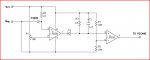
Concept: My idea is to have a sound detector (mic, amplifier kit Rm35 or AUD12) adjacent to the GPS. The output of the amp will go to the Picaxe 08 for processing.

The role of the 08 is to determine that it is the GPS alarm that it is hearing, not miscellaneous wind or wave noises. I propose to have the 08 sleeping, and possibly use an interrupt to wake it up. I'll have to read Stan's article again. With the 08 awake, it will measure pin3 and get a 1. Wait a second it will get a 0. If I measure 8 times and get 4 1's then it is an alarm.

Should I sample at a higher rate?? How do I remove the need to measure the time of a cycle fairly accurately?

If it's a valid alarm, the 08 will close the switch on a wireless doorbell. (A Chinese battery powered set cost me Rm12 or AUD3.).

I would appreciate any further ideas for the project.
 

Pauldesign

Senior Member
Hey Meridain,

The alarm from my GPS (Furuno) beeps on a roughly 1 second cycle.
You'll have to determine the the beeping freq (Use a scope or spectrum analyzer). Note, the duty cycle of the beep sound can be 1 Hz and not the freq. Humans can't even hear 1Hz!

I would appreciate any further ideas for the project.
- I believe you and or you're mate aren't totally deaf since you're using hearing aids; which means there are certain frequencies that you guys ear can perceive or response to. Note human hearing mechanism is just a band pass filter within the range of 22Hz to 22kHz.

I believe you guys ear can pick up frequency of a particular tone than other freq. That frequency can be filter out with a very narrow band pass filter and then amplified.

With an assistant, a signal generator can be use to deduce what frequency you may hear by gradually applying a frequency sweep between 22 Hz to 22 KHz at 10 Hz or any suitable increment.

- Note, low frequecies below 100 Hz are more felt than perceived. Which means such frequencies can can cause vibrations which can be perceive by your body.

Therefore, you may design a low 100 Hz (you'll have to experiment to find suitable freq) low pass filter and then amplified it and connect it to a suitable piezo sensor and attached it to your body.

- You should also add visual indication. A flashing LED will be nice. It must be flashing as that will call more attention and convey more info.

To conclude, simply use RF to encode and transmit the 1 sec beeping pulse from your GPS with a picaxe. The pulse can be received by a RF/picaxe/sensor combo circuit strap to a suitable part of your body. This circuit will have an LED to provide visual ind and a piezo to provide both Audio and vibrational indication.

There are lots of other ideas or work around and good luck with your project.

You're more than welcome for further questions ;)
 

hippy

Ex-Staff (retired)
You'll have to determine the the beeping freq (Use a scope or spectrum analyzer).
That seems the best way; a high-Q bandpass filter so the output goes higher when the frequency of the alarm signal is present, is low ( 'off' ) otherwise. It can be analogue output or passed through a comparator to give a digital high/low; depends if you want to do level detection in hardware or software. Software gives more flexibility.

All you then have to do is look for the presence of the tone to know the alarm is going off.

This can then be improved by checking that the alarm signal is of the right period, even with the right gaps to remove false triggering when the frequency appears in the normal audio.

Your project then becomes four parts -

1) Hardware microphone amp, filter and indicator
2) Software 'alarm' detector
3) False alarm removal
4) Alert generation

The false alarm removal part isn't absolutely necessary and can be done last so you can have a working, but not perfect, solution before setting sail. That may help as it's a short deadline.
 

techElder

Well-known member
Why don't you just put a microphone in close proximity to the 'alarm' audio output device and run it into one of those amplifier that the young ones put into their cars? God knows we can all hear those damn things (even wake the dead!)

Just make your 'alarm' audio LOUDER!
 

meridian

Member
That seems the best way; a high-Q bandpass filter so the output goes higher when the frequency of the alarm signal is present, is low ( 'off' ) otherwise. It can be analogue output or passed through a comparator to give a digital high/low; depends if you want to do level detection in hardware or software. Software gives more flexibility.


This can then be improved by checking that the alarm signal is of the right period, even with the right gaps to remove false triggering when the frequency appears in the normal audio.

Your project then becomes four parts -

1) Hardware microphone amp, filter and indicator
2) Software 'alarm' detector
3) False alarm removal
4) Alert generation

The false alarm removal part isn't absolutely necessary and can be done last so you can have a working, but not perfect, solution before setting sail. That may help as it's a short deadline.
I have bought a sound level kit which uses a LM356 opamp with a 3914 LED driver at the back. I'll put the 08 there instead. Ideas for a hi-Q cct would be appreciated.

You're absolutely right, the fine tuning can come later. I was going to try using 433MHz Tx/Rx pair to send info then had the bright idea of a wireless doorbell. Cheap too!
 

meridian

Member
Hey Meridain,


You'll have to determine the the beeping freq (Use a scope or spectrum analyzer). Note, the duty cycle of the beep sound can be 1 Hz and not the freq. Humans can't even hear 1Hz!


- I believe you and or you're mate aren't totally deaf since you're using hearing aids; which means there are certain frequencies that you guys ear can perceive or response to. Note human hearing mechanism is just a band pass filter within the range of 22Hz to 22kHz.

I believe you guys ear can pick up frequency of a particular tone than other freq. That frequency can be filter out with a very narrow band pass filter and then amplified.

With an assistant, a signal generator can be use to deduce what frequency you may hear by gradually applying a frequency sweep between 22 Hz to 22 KHz at 10 Hz or any suitable increment.

- Note, low frequecies below 100 Hz are more felt than perceived. Which means such frequencies can can cause vibrations which can be perceive by your body.

Therefore, you may design a low 100 Hz (you'll have to experiment to find suitable freq) low pass filter and then amplified it and connect it to a suitable piezo sensor and attached it to your body.

- You should also add visual indication. A flashing LED will be nice. It must be flashing as that will call more attention and convey more info.

To conclude, simply use RF to encode and transmit the 1 sec beeping pulse from your GPS with a picaxe. The pulse can be received by a RF/picaxe/sensor combo circuit strap to a suitable part of your body. This circuit will have an LED to provide visual ind and a piezo to provide both Audio and vibrational indication.

There are lots of other ideas or work around and good luck with your project.

You're more than welcome for further questions ;)
Thanks for your suggestions Paul. Space is pretty limited on a yacht, so no scope, signal generator or other test gear. Although when we set out nearly 11 years ago, I did actually take a scope with me. With no real need, it got dumped.

The wireless doorbell goes ***DING-DONG***!!!! with flashing light; I think I'll notice that - no need for sensors.
 

hippy

Ex-Staff (retired)
If your input filter is manually adjustable for frequency, such as with a pot, you can simply set the alarm going and adjust for maximum output. Someone with a "good sense of musical scale" should be able to tell you what the ball park frequency is for the starting design parameters.

For high-Q bandpass filters - Google is your best bet; plenty of circuits there. Choose something simple given the timescale, build on a separate PCB / stripboard and you can upgrade it later if needed. You can use a single board but make sure each area is self contained and can be removed / bypassed.
 

SAborn

Senior Member
One thing i used recently as a sensor was a piezo and found it very good and adjustable in sensitivity.

So instead of a mic perhaps a piezo feeding into the opamp with a cap to create a filter to latch the input signal.

One would expect piezo to piezo would work better for this application then piezo to mic.

The rest is just as little programming for the 08m and as hippy said can be debugged as you go.

Here is the basic Piezo to opamp circuit i used that allowed me to adjust the sensitivity.
 

Attachments

meridian

Member
One thing i used recently as a sensor was a piezo and found it very good and adjustable in sensitivity.

So instead of a mic perhaps a piezo feeding into the opamp with a cap to create a filter to latch the input signal.

One would expect piezo to piezo would work better for this application then piezo to mic.

The rest is just as little programming for the 08m and as hippy said can be debugged as you go.

Here is the basic Piezo to opamp circuit i used that allowed me to adjust the sensitivity.
Many thanks for that idea, sounds like just what I need. What I also need is a 358. The kit I have has a LM356, will that work? I haven't looked up the datasheets for either. Needless to say, Miri is not the best place to buy such things. I have some piezos, discreet transistors and various resistors and caps, so should be able to cobble something together along the lines of the Rev-Ed SSDC.
 

SAborn

Senior Member
Are you sure its a LM356 opamp as i did not see a listing for a 356 on a quick search.

The lm358 is a opamp that will work from a single power supply with close to rail to rail operation, but basically any opamp should work in the circuit that will operate from a single supply.

It could even be a compariator, as its only there to boost the input signal to the picaxe.
 

krypton_john

Senior Member
Just put out more chain. The anchor won't drag unless it's a howling storm in which case you'll be taking turns on watch and wide awake anyway.

:)
 

meridian

Member
Anchor alarm update

Well here we are in Penang, 3 weeks and 1200 nautical miles down the track. After much help from SAborn Peter (unfortunately no result) and much frustration, I have an almost working alarm.

SAborn gave me a cct with a BC547 to amplify the sound from the alarm. The sound level wasn't high enough and it just wouldn't work.

Last week we were in Singapore's Sim Lim Tower (famous place) where I bought a Voice-activated switch kit, Future Kit FK408 (http://futurekit.com/2009/manual/future/eng/PDF_FK4/fk408e-1.pdf)

Picture at http://futurekit.com/2009/images/stories/product/4/big/FK408b.jpg. It uses an LM 324 chip.

The instructions were in Thai! but I found the English ones on the website. It went together well except for one missing resistor and worked first time!

As I predicted, sensitivity and false triggering were a problem as it stood. Even the relay clicking on and off was enough to generate a self-perpetuating cycle. Clearly it was time for Super08!

I took the LED voltage, put it through an opto and fed it to the '08. The '08 output went back in to the transistor driving the relay. The relay in turn supplies 12V to the wireless doorbell transmitter. That was the simplest, easiest and cheapest alarm, RM12 or $3.

As Hippy said:
Your project then becomes four parts -

1) Hardware microphone amp, filter and indicator
2) Software 'alarm' detector
3) False alarm removal
4) Alert generation

I have most of these, in fact last night I thought I had them all after playing with timing of adc reads. The GPS alarm sounds for 2 secs, off for .5 sec as best I can estimate (no CROs on board). I sample three times within each beep for three beeps. If I get 7 or more counts, the alarm sounds. In very quiet conditions, three alarm beeps set off the alarm. Great!

We are anchored off Penang, near the airport and under the flight path. A constant roar from the jets sets off the alarm. So, back to hippy's point 1, filtering.

The input to the first stage from the mic is a 10uF cap and 30K resistor to pin2, with 22uF and parallel 30K from pin3 to ground, and a 5M feedback from 1 to 2.

The piezo in the GPS is fairly high pitched, 1000Hz?? I am out of my depth here, so am about to stand by for collective wisdom of the Axemen.
 

inglewoodpete

Senior Member
I feel really sorry for you, floating around the tropics with problems like yours! <insert jealous icon here>

Most piezo beepers have a resonant peak of around 3 to 3.5 kHz. Are you able to put a band-pass filter on the amplifier to minimise other frequencies? Or hard-wire the amplifer input via a couple of low value capacitors (1nF to 10nF) to the piezo terminals?

FWIW, on 1,000Hz. If you remember back to when radio and TV stations shut down for the night (I'm showing my age), they would play a tone for a short while (and sometimes a test pattern for TVs). That tone was usually around 1,000Hz. To do it another way, a low whistle (human, pursed-lips-type) is roughly 1kHz.
 

Andrew Cowan

Senior Member
What are you using for your microphone?

You can use a piezo speaker as a microphone - and if you do this, it will produce the greatest responce to it's resonant frequency. Therefore if you buy a piezo with a resonant frequency of 1kHz, it will give the highest reading when a 1kHz sound is detected.
 

techElder

Well-known member
Somewhere in here, someone has to mention the iconic name of Rube Goldberg. :D

I know it's not as much fun, but you already have the GPS alarm ... just amplify it, run two speaker wires to your pillow and put the speaker there!

PS. You could add an LCD and a bunch of buttons ... just for fun.
 

inglewoodpete

Senior Member
Steady bro. People are trying to help. And yes, I can tell it's frustrating.

Remember, you are living this problem. Forum members are not: they are picking up a thread that they have forgotten about for 2 weeks. We probably won't remember or read the thread from end to end before replying.

I still think I gave you some useful information about the resonant frequency of typical piezos. Some acknowlegement would help. Tune your mike/audio to that and you have a chance.
 
Last edited:

techElder

Well-known member
For those who came in late, ... Introduction: One of the hazards of anchoring is that wind and tide can exert forces on the vessel exceeding the holding power of the anchor. This causes the boat to move, sometimes in unhelpful directions in which lie reefs or rock or shore (and *always* in the middle of the night). To guard against such events, the GPS has an 'Anchor alarm' which sounds if your position moves away from the anchored position by a specified distance, ie .02 or .03NM or 40 or 60 metres. The alarm from my GPS (Furuno) beeps on a roughly 1 second cycle. There is no wire available externally.
THERE IS NO ALARM!!! Otherwise, why would I be going through all this??!?!?!?!?
Perhaps the problem is that you don't think you know how to get the "alarm" noise out of your GPS? That seems almost trivial to me.

Sorry for upsetting you, but I have been reading along.
 

techElder

Well-known member
Open GPS case.
Find beeper.
Connect wires.
Add appropriate voltage divider (2 resistors).
Add jack if wanted.
Close GPS case.
Connect wires to audio amplifier input.
Run audio amp output with wires to external "pillow" speaker.
Rest easy.
 

meridian

Member
What is the exact model number of your Furuno GPS unit?

:) joe
It's a Furuno GP-31, now 10 years old. The wiring diagram shows no alarm output. And for further information, the piezo is buried under shielding so inaccessible. I looked.

According to the FK circuit, the mic is a condenser. I will try a piezo as a mic and see how it goes.
 

meridian

Member

meridian

Member
Game,set and match

What are you using for your microphone?

You can use a piezo speaker as a microphone - and if you do this, it will produce the greatest responce to it's resonant frequency. Therefore if you buy a piezo with a resonant frequency of 1kHz, it will give the highest reading when a 1kHz sound is detected.
Thank you Andrew, I tried the one and only piezo on hand, and was not confident when it wouldn't squark with 4.5V or 9V. Anyway I wired it in, attached it to the rear of the GPS with Blu-Tak (TM) and BINGO! As you said, it is resonant with the GPS and pretty deaf to everything else.

It consistently sounds the doorbell after 3 or 4 beeps while not a flicker from any other noise.

Thanks to inglewoodpete for the cap suggestion, but changing the mic was the easiest thing to try.


With that I will close the case by saying thanks to all who contributed, particularly SAborn. Apologies to Mt Hopper for the intemperate shouting. Its been a hard 3 weeks travelling nearly every day. So far we have covered around 1200 NM. I don't have a workshop so all work has to be done on the saloon table, then put everything away before setting out the next day. Its a hard life!

Thank you linesmen, thank you ballboys.
 

Andrew Cowan

Senior Member
I'm glad that worked - it was an untested theory I came up with. It's a good solution.

The only problem now is... ...what happens when the blu-tak (TM) falls off :confused:?

Andrew
 
Top