PhilHornby
Senior Member
I've been doing some investigation into my Hyundai Tucson's PKES system. The key fob is supposed to be equipped with a 'sleep mode' to defend against Relay Attacks, but I was struggling to demonstrate this. The obvious solution, was to capture the signal from the car door lock, decode it and reproduce it on a Picaxe ")
(In a nutshell, the car sends out a OOK-modulated 125KHz 'signal' and the fob responds using its battery-powered 433MHz transmitter. There is apparently usually more than one handshake in the sequence, but I was only interested in there being any kind of response).
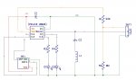
AIUI, the 125KHz signal emanates as a magnetic field, rather than a radio wave - so rather like a Current Transformer (the so-called 'Near Field'). I bought myself a pre-wound 'RFID' coil and spent happy hours searching for the optimum capacitor to tune it to 125KHz. Since the coil has a DC resistance of only 7Ω, I used a series L-C arrangement, directly connected to a Picaxe output. I ended-up with a 30VPk-Pk signal across the coil and nothing scary at the Picaxe.
I borrowed the Data Signal Modulator approach from this thread to create my 125KHz signal. Adding a Hope 433Mhz RF receiver allowed me to detect the Fob's response and "the job's a good 'un!" as the saying goes...
I achieved everything I hoped to - including a 60cm range, just using a Picaxe output. However...
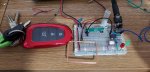
I moved my circuit from my main Breadboard onto a smaller one, as a precursor to making a PCB for it. At this point, it stopped working.
I soon discovered that it worked with the AXE027 plugged into the AXE029, but stopped working when that was unplugged. It was when I discovered that the AXE027 didn't need to be plugged into the PC end to make it work, that I realised that this isn't a simple wiring issue (such as a bad earth). For all the world, it seemed like I was generating a 125KHz Radio signal and the AXE027 acts as an aerial. (An old PSU with a mono jack plug also works!)
At this point, I thought: So what exactly is the coil bringing to the party then? Sure enough it does work with the coil removed, but only if the associated capacitor (C2) is connected to GND. The range drops considerably in this mode, to 10cm or so.
What have I built - and more to the point, what should I do to get rid of the need for an AXE027 to be plugged in
(In a nutshell, the car sends out a OOK-modulated 125KHz 'signal' and the fob responds using its battery-powered 433MHz transmitter. There is apparently usually more than one handshake in the sequence, but I was only interested in there being any kind of response).
AIUI, the 125KHz signal emanates as a magnetic field, rather than a radio wave - so rather like a Current Transformer (the so-called 'Near Field'). I bought myself a pre-wound 'RFID' coil and spent happy hours searching for the optimum capacitor to tune it to 125KHz. Since the coil has a DC resistance of only 7Ω, I used a series L-C arrangement, directly connected to a Picaxe output. I ended-up with a 30VPk-Pk signal across the coil and nothing scary at the Picaxe.
I borrowed the Data Signal Modulator approach from this thread to create my 125KHz signal. Adding a Hope 433Mhz RF receiver allowed me to detect the Fob's response and "the job's a good 'un!" as the saying goes...
I achieved everything I hoped to - including a 60cm range, just using a Picaxe output. However...
I moved my circuit from my main Breadboard onto a smaller one, as a precursor to making a PCB for it. At this point, it stopped working
.I soon discovered that it worked with the AXE027 plugged into the AXE029, but stopped working when that was unplugged. It was when I discovered that the AXE027 didn't need to be plugged into the PC end to make it work, that I realised that this isn't a simple wiring issue (such as a bad earth)
. For all the world, it seemed like I was generating a 125KHz Radio signal and the AXE027 acts as an aerial. (An old PSU with a mono jack plug also works!)At this point, I thought: So what exactly is the coil bringing to the party then? Sure enough it does work with the coil removed, but only if the associated capacitor (C2) is connected to GND. The range drops considerably in this mode, to 10cm or so.
What have I built - and more to the point, what should I do to get rid of the need for an AXE027 to be plugged in
Last edited: