Analogue Clock

Buzzer

Member
Hi all,

Just wanted to know if making an analogue clock was feasible or not by using two servos (for hands) and servo out on a loop.
Not made it, and don't even have the parts, just wondering if I won't waste time by writing a program and getting the parts.
I can imagine a digital clock being easier, but I would prefer to have it as an analogue clock, for presentation.

Comments?

Cheers
 

KeithRB

Senior Member
Hi all,

Just wanted to know if making an analogue clock was feasible or not by using two servos (for hands) and servo out on a loop.
Not made it, and don't even have the parts, just wondering if I won't waste time by writing a program and getting the parts.
I can imagine a digital clock being easier, but I would prefer to have it as an analogue clock, for presentation.

Comments?

Cheers
I think you want a stepper motor, not a servo. Most servos cannot rotate 360 degrees. I think the hard part will be to get concentric shafts.
 

Buzzer

Member
Thanks for the heads up on servos.

Stepper motor looks like way too much trouble for this, I guess I'll give this one a miss for now, I will try this another day, unless there's any other type of motor.

Thanks for the quick reply
 

KeithRB

Senior Member
No one said it had to be the traditional clock that is 360 degrees. You could make one that had 1-12 on a 180 degree Arc, or whatever.
 

Buzzer

Member
If using a stepper motor, could I control how much it 'steps' by? i.e, to make each step 6 degrees per minute.
If so, how? If not, how could I achieve the above situation?
 

g6ejd

Senior Member
You might want to explore Analogue clocks that are driven by an MSF Time Receiver, they are driven by a series of pulses; hours and minutes independently, so that's both hands from an on-board receiver with CPU to handle the time code decoding. Remove the receiver and figure out the connections, then drive it yourself with your own code. You should be able to buy one for about £10 in the UK, seen a few at £8.95.

You can also buy the clock modules with hands for about the same price, I guess buying a ready made clock that you can then dismantle for your own clock face in time/when it's running - easier for development too.
 
Last edited:

goingsolo

Member
Its easy enough to modify a servo for 360 degree rotation - a google search should provide instruction. This usually involves removing the internal potentiometer and cutting out the mechanical stop. The problem with this is that you'll need a way to detect the position of the servo. Maybe some kind of an optical encoder.

The problem with stepper motors is that a step is typically 1.8 degrees. Since one minute is 6 degrees this doesn't work out very well since 1.8 doesn't divide into 6 evenly.
 
Last edited:

Buzzer

Member
@Buzzer

Did you manage to get the 08M2 problem sorted?
http://www.picaxeforum.co.uk/showthread.php?20390-08m2-HELP/page2

e
Not quite, I'm afraid. The chip gets hot when I just power it up, so I guess it's probably a broken chip, although why all three are broken is beyond me. Perhaps it may be something else, I will keep trying.

In regards to the stepper motor, as highlighted by goingsolo, the stepper motor would not step properly for me.

Check out this great clock.

http://www.picaxeforum.co.uk/showthread.php?11740-Card-Clock

uses 3 servos and a deck of playing cards!
This really is incredible!!

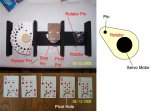
Just to ask, how does he make the cards fan out by using the pivot holes? The maker, Alpacaman, has explained it, but I still don't really understand.

Thanks
 

BillyGreen1973

Senior Member
The problem with stepper motors is that a step is typically 1.8 degrees. Since one minute is 6 degrees this doesn't work out very well since 1.8 doesn't divide into 6 evenly.
Whilethis statement is correct, using a stepper motor with a 1.8deg step woudn't be such a problem.
1.8 DOES divide equally into 45, 90, 135, 180 etc. So the Min hand would be correct when at the 12, 3, 6, and 9 positions (and half way between them). If these were the only numbers on the clock face, the observer wouldn't be able to see any error between them.
Also, conveniently, 360deg at 1.8deg per step is 200 steps. Making the maths easy for the picaxe to control.
 

westaust55

Moderator
If using a stepper motor, could I control how much it 'steps' by? i.e, to make each step 6 degrees per minute.
If so, how? If not, how could I achieve the above situation?
With a stepper motor having a 1.8 degree "normal" step (200 steps per revolution) the best you could achieve is to use a stepper motor driver for microstepping.
At 1/16th steps (ie microstepping) the 6 degrees per minute would still be 53.33333 steps per minute so would would need to have a cycle of 53, 54 and 53.
That would give around 0.037 degree retarded error at minute 1, then 0.037 advance error at minute 2 and at the correct position at minute 3.
There have been posts here in the past covering stepper motor controllers with micro-stepping capability. A search is in order.
 

hippy

Ex-Staff (retired)
@Buzzer

Did you manage to get the 08M2 problem sorted?
http://www.picaxeforum.co.uk/showthread.php?20390-08m2-HELP/page2

e
Not quite, I'm afraid. The chip gets hot when I just power it up, so I guess it's probably a broken chip, although why all three are broken is beyond me.
That does sound like a hardware or circuit fault as PICAXE chips should not get hot.

It would probably be best to update the original thread with that and any other relevant information and then people can help with continuing to investigate the problem.
 

goingsolo

Member
Whilethis statement is correct, using a stepper motor with a 1.8deg step woudn't be such a problem.
1.8 DOES divide equally into 45, 90, 135, 180 etc. So the Min hand would be correct when at the 12, 3, 6, and 9 positions (and half way between them). If these were the only numbers on the clock face, the observer wouldn't be able to see any error between them.
Also, conveniently, 360deg at 1.8deg per step is 200 steps. Making the maths easy for the picaxe to control.
This wouldn't be too noticable with the minutes hand but the hour hand might be a little more noticable - I don't know for sure. I've been wanting to make a clock similar to the one found at http://www.amazon.com/suc-Eye-Clock/dp/B0031AW91Y. Which is why this thread caught my eye.
 

BillyGreen1973

Senior Member
Well, having just looked at the 'Eye Clock' there is no way of telling where the hour 'Pointer' is actually pointing with any accuracy.
As for the hour hand on a traditionalclock face being 'off' slightly, this is easily solved by putting '1' and '2' markings where the hand points to, instaed of evenly spaced. The difference would hardly be noticable, but at 1 o'clock the hour hand would point to the 1, for example.
 

goingsolo

Member
Well, having just looked at the 'Eye Clock' there is no way of telling where the hour 'Pointer' is actually pointing with any accuracy.
As for the hour hand on a traditionalclock face being 'off' slightly, this is easily solved by putting '1' and '2' markings where the hand points to, instaed of evenly spaced. The difference would hardly be noticable, but at 1 o'clock the hour hand would point to the 1, for example.
I think you're right - it's a matter of playing around with it. Attached are 2 versions of the eye clock I was thinking of makingBettyBoopClock.jpgHomerEyeClock.jpg
 

goingsolo

Member
The pivot hole in the card goes over the pivot pin. The stop pin sits in the arch cut out in the card. Due to gravity the card will want to fall CCW. You can insure this by placing the pivot hole in the card a little bit to the right of center. The left side of the card will rest on the rotator pin. As the servo turns the rotator the cards will fan out.
CardClock.jpg
 
Top