air flow speed measurement
- Thread starter tparvais
- Start date
Commercial air flow sensors often use heated wires (one in the air stream, one shielded from it). You measure the resistance change of the wire in the air stream to determine air flow. This requires detailed calibration of each device and some relatively sophisticated electronics, thus the high price.
One alternative is a "wind speed" meter (using a DC generator driven by a propeller in the air stream). There are commercial meters for handheld use that are under $70US
http://www.weatheressentials.com/index.asp?PageAction=VIEWPROD&ProdID=28
If the turbine and its housing do not significantly impede the air flow, the turbine portion of the meter could be removed and mounted in the duct, with the display mounted remotely.
Depending on the accuracy needed, you might be able to use a DC motor and propeller (look for "solar motor" at the various electronics and kits suppliers) whch could be placed in the duct and the PICAXE could measure the output of the motor (used as a generator). For calibrated air flow measurements, you would need something like the wind speed meter (above) to create the lookup table for the PICAXE (generator output versus feet/sec or meters/sec of air flow).
John
How about a piezo disk with some sort of baffle (a needle or nail will do) glued to the centre projecting outwards perpendicular to the disk. The disk is fixed to the inside of the duct by it’s edges and the baffle is projected into the airflow. An audio pre-amp with low pass filter and peak-detector into a PICAXE ADC would give you a rough idea of air speed. It would need to be calibrated first, maybe on a bicycle or out of the window of a car. Dead simple, dead cheap. I was thinking of trying something similar to measure air-speed on a model RC aircraft. Worth an experiment?
Rickharris
Senior Member
Why not a flap in the air stream attached to the spindle of a suitable potentiometer, you can read the value of the pot with readadc.
The greater the air flow the higher the flap will rise. Make it very light e.g. polystyrene to be sensitive.
The greater the air flow the higher the flap will rise. Make it very light e.g. polystyrene to be sensitive.
Hello
Very interesting ideas
-Boriz, I see what you mean, but I remember from University, Piezo disk is not easy to work with and not easy to find ?
-ceke: indeed, but you will need a convergent duct or wahtever. See http://gatt.club.fr/page1/page28/page28.html#paragraphe2.2 (in french byt very <ell done)
-Rickharris: is there potentiometer without mechanical resistance ? otherwise, the mechanism will perturbate the measurement
In fact, I'm thinking to use strain gauges glued on a small piece of metal placed in air flow. See http://en.wikipedia.org/wiki/Strain_gauge
I already used strain gauges 10 years ago to control 6 legs walking robot in research labs. Very "easy" to use when inserted in Wheatstone bridge. most difficult is to glue them properly on the support
Thomas
BeanieBots
Moderator
"Commercial air flow sensors often use heated wires" as stated by papaof2.
A "poor mans" version is a self heating thermistor.
Either option would present the least disruption to air flow.
A "poor mans" version is a self heating thermistor.
Either option would present the least disruption to air flow.
Here's one circuit http://www.edn.com/archives/1996/031496/06di3.htm
krypton_john
Senior Member
I would have thought a simple and cheap approach was to adapt an ultrasonic rangefinder. Ping an ultrasonic sound pulse in each direction and measure the time difference.
There's plenty of no-moving-parts wind speed and direction examples of this around that use 2 pairs at right angles and triangulate the wind speed and direction.
There's plenty of no-moving-parts wind speed and direction examples of this around that use 2 pairs at right angles and triangulate the wind speed and direction.
IIRC I breadboarded it as a curiosity and saw that it would work, but have never actually used it. He has published several similar designs http://electronicdesign.com/Authors/Index.cfm?AD=1&AuthorID=934&DisplayTab=Authors, most recently one in 2001 that has dc output and may be more suitable.LizzyB: I have seen the EDN circuit offered as a solution in the past, but I have never seen anyone tell of a successful (or otherwise) use of the circuit. Have you used it or know of someone who has (excepting the author)?
inglewoodpete
Senior Member
In reply to the original question...
A recent issue of Silicon Chip magazine had an article in the "Circuit Notebook" (reader's projects) column. The circuit used a small incandescent light bulb as a sensor, configured as the top leg of a voltage divider. A PICAXE (or was it a PIC?) was used to read and interpret the readings.
For a more accurate readout, you may need to include a DS18B20 air temperature sensor as well.
Andres Rodriguez
New Member
Depending on the estimated airspeed you could use the MPX 2010 sensor from Freescale Semiconductor (ex Division of Motorola). They are pitot tubes and the resistance varies according to the difference between static and dynamic air pressure. The most sensitive (MPX 2010)works well above 40 Miles per hour. The output voltage is very low and you will need to create a circuit to amplify the output and feed it to a Picaxe adc pin.
http://www.freescale.com/files/sensors/doc/data_sheet/MPX2010.pdf?fsrch=1
I am working on a project to meassure airspeed on an RC airplane and can send you the schematic of the amplifier circuit
http://www.freescale.com/files/sensors/doc/data_sheet/MPX2010.pdf?fsrch=1
I am working on a project to meassure airspeed on an RC airplane and can send you the schematic of the amplifier circuit
Marmitas, yes please, can you send me the schematic of your board ?....
http://www.freescale.com/files/sensors/doc/data_sheet/MPX2010.pdf?fsrch=1
I am working on a project to meassure airspeed on an RC airplane and can send you the schematic of the amplifier circuit
Thank you
Thomas
Replace op-amps with PICAXE?
The above links to airflow measurement describe analog circuitry that compares the temperature between a heated reference transistor and one exposed to the airflow. (linearization is also provided in some examples). Would it be possible to replace many op-amps and other discrete components by using PICAXE analog inputs for the comparison, with a look-up table if real-time linearization was required?
The above links to airflow measurement describe analog circuitry that compares the temperature between a heated reference transistor and one exposed to the airflow. (linearization is also provided in some examples). Would it be possible to replace many op-amps and other discrete components by using PICAXE analog inputs for the comparison, with a look-up table if real-time linearization was required?
Andres Rodriguez
New Member
PD0 connects to a Picaxe analog input pin
Attachments
-
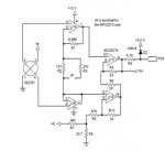 30 KB Views: 48
I meant replacing airflow, rather than air pressure, analog circuitry with a PICAXE. If it was possible to compare (in software) the temperature of the two sensors required for airflow measurement, it could offer a lower component count solution. If you did not need linearization, an 08M might even manage the task and output serial data to the 'main' microcomputer. Just an idea that my limited programming skills would probably not be up to implementing anyway.
Rickharris
Senior Member
i think - or am happy to be corrected that in most general pots the "stiffness" is created by the addition of a special grease to the shaft - if you dismantle the pot clean out the shaft and bush and add a more lubricating product you should have your easy operation pot.
I havn't got a pot to hand to prove this at present but will look at school tomorrow.
I havn't got a pot to hand to prove this at present but will look at school tomorrow.
Rickharris
Senior Member
Ok addition went and found a pot in the garage - old type but had no "grease" a little lubrication on the back plate and some careful re assembly without crimping the parts back too tightly produced a fairly easy turn pot.
Multi turn pots tend to be very free running.
OR why not a fan on a solar motor the resulting voltage will be proportional to the air speed.
Multi turn pots tend to be very free running.
OR why not a fan on a solar motor the resulting voltage will be proportional to the air speed.
Just to add to the flap idea, maybe a light interrupter mounted to the flap shaft so to block light to an LDR when no air flow and give full light at the maximum, would also be possible to fit a aquadratic encoder disc to the shaft to monitor the flap position. Both options don't add any resistance to the flap movement.Why not a flap in the air stream attached to the spindle of a suitable potentiometer, you can read the value of the pot with readadc.
The greater the air flow the higher the flap will rise. Make it very light e.g. polystyrene to be sensitive.
Last edited:
Marmitas,PD0 connects to a Picaxe analog input pin
Have you had a chance to test your circuit yet? I'm looking for something compact for a sailing (rc) application. Looks like a good start.
Andres Rodriguez
New Member
TSWEENEY,
Yes I tested it as follows:
I wrote code to read the voltage outpu ton Pin AD0 and display the information on an LCD.
Then I attached a rod that ended 4 feet forward of the front of my car (not legal in NY)to get clean air. I taped a 1/4" ID flexible tube to the rod with the one end facing forward and the other end attached to the dynamic pressure inlet of the sensor. A friend drove the car from 40 to 75 miles an hour in increments of 5 miles an hour. I recorded the readings I was getting on the LCD on a piece of paper. We repeated the reading in the oposite direction on the same highway. Then using Xcell I ploted the data and created the calibration equation (it is a parabola). I have not tested it in an airplane but that is next. I hope this helps, if you need more detailed info, send me a PM
Andrés RodrÃguez
Attachments
-
12.5 KB Views: 32
andrew_qld
Senior Member
I am pretty sure I saw a "hot wire" airflow sensor made from an old 6V light globe (with glass removed) using a picaxe in Silicon Chip magazine recently. Just went to have a look and their website is down.
Hello,TSWEENEY,
Yes I tested it as follows:
I wrote code to read the voltage outpu ton Pin AD0 and display the information on an LCD.
Then I attached a rod that ended 4 feet forward of the front of my car (not legal in NY)to get clean air. I taped a 1/4" ID flexible tube to the rod with the one end facing forward and the other end attached to the dynamic pressure inlet of the sensor. A friend drove the car from 40 to 75 miles an hour in increments of 5 miles an hour. I recorded the readings I was getting on the LCD on a piece of paper. We repeated the reading in the oposite direction on the same highway. Then using Xcell I ploted the data and created the calibration equation (it is a parabola). I have not tested it in an airplane but that is next. I hope this helps, if you need more detailed info, send me a PM
Andrés RodrÃguez
This is very interesting. I have found small Pitot tube. But the air flow speed is max. 5m/s in the air duct. This means a very small delta-pressure on the Freescale sensor (few Pascal). I'm not sure it is good enough for that application.
Thomas
5 m/s (I'm assuming meters/sec, not miles/sec ;-) is about 5MPH/8KPH, which probably won't be enough for a pitot tube.
Look for a solar motor kit with fan blades that will fit (or can be adapted to fit) in the duct. Use it as a generator with the air flow in the duct turning the fan. Put a low value resistor (100R - 330R) across the output of the motor to provide a load and use ADC to measure the voltage produced.
John
Rickharris
Senior Member
I think I said that as well ! great minds think alike.5 m/s (I'm assuming meters/sec, not miles/sec ;-) is about 5MPH/8KPH, which probably won't be enough for a pitot tube.
Look for a solar motor kit with fan blades that will fit (or can be adapted to fit) in the duct. Use it as a generator with the air flow in the duct turning the fan. Put a low value resistor (100R - 330R) across the output of the motor to provide a load and use ADC to measure the voltage produced.
John
")
"I think I said that as well ! great minds think alike. "
Nice to be included in the great minds ;-)
Depending on the actual application, another possibility might be using a device modelled after a water tube barometer (U-shaped tube filled with water - or a less-evaporative liquid of similar specific gravity), with the airflow across one end of the tube providing the pressure difference from ambient atmospheric pressure.
connection_to_duct--u--open_to_room
Sensing the water level in the tube could be a challenge; if the application is a go/no-go measurement, then add some colorant to the water and use a single LED and photodiode/phototransistor to detect the water level. Multiple discrete levels could be sensed with multiple LED/detector pairs, or - if the water tube is large enough - a floating magnet could move past a Hall effect sensor and give a continuously variable measurement (within the sensitivity limits of the Hall effect device).
John
"Nice to be included in the great minds ;-)
Depending on the actual application, another possibility might be using a device modelled after a water tube barometer (U-shaped tube filled with water - or a less-evaporative liquid of similar specific gravity), with the airflow across one end of the tube providing the pressure difference from ambient atmospheric pressure.
connection_to_duct--u--open_to_room
Sensing the water level in the tube could be a challenge; if the application is a go/no-go measurement, then add some colorant to the water and use a single LED and photodiode/phototransistor to detect the water level. Multiple discrete levels could be sensed with multiple LED/detector pairs, or - if the water tube is large enough - a floating magnet could move past a Hall effect sensor and give a continuously variable measurement (within the sensitivity limits of the Hall effect device).
John
Mpx5010
Sorry to resurrect this thread, but this seemed topical: I noticed earlier in the thread the MPX2010 was suggested. I happened across the MPX5010 which appears to have the same input pressure range but gives a 0V - 5V output ideal for direct connection to a PICAXE ADC and would hence allow the additional amplification circuitry to be skipped. Am I correct in thinking this, or is there something I've overlooked?
Datasheet is here.
Many thanks!
Andres Rodriguez
New Member
You are right. I also changed from the old sensor (required a signal conditioning circuit) to the new one which has a built in signal conditioning. The other advantage is that the output voltage is proportional to the pressure (straight line)
The one I was using with an external circuit had an out put that followed a cuadratic expression (parabola).
The one I was using with an external circuit had an out put that followed a cuadratic expression (parabola).
Well ... the easy way is to just get A MAF from a junk yard car and calibrate it after you put it into the air stream. It should only cost ~ $5 and it will put out a very nice 0-5v signal. If you can get one off of a Ford Escort 1.9L in the 1991-95 vintage I already have the flow charts v. voltage and all you will need to do is scale it to your volume.
Most of the cars from 91 up with fuel injection use them. They operate from 12v using a hot wire but all in a nice package.
Most of the cars from 91 up with fuel injection use them. They operate from 12v using a hot wire but all in a nice package.