Adjustable PWM Motor Controller

Mejlby

Member
hi all

is there anyone who can help me with code (complete program) for a PWM motor controller where I can adjust the duty cycle from 0 to 100% with a 5K (or 10K) potentiometer.

I want to make a PWM controller that can provide 1kHz with rise and fall times approximately 200 ns

I would be very grateful for help with this ;)

Tonny
Denmark
 

Dippy

Moderator
Well, there is two parts to this. No.1: Your electronic driver circuit and component choice will (mostly) define the rise and fall times.
Please post your circuit.
We'll need to know what power output (I and V) you are hoping to produce.
Is this "200nS" on the Gate (assuming MOSFET/IGBT) or the final output to the load? The final characteristics will depend on load, wiring, your PCB layout, PSU, wind direction ... all sorts). It can be easy or blooming hard, so more details please.


The Manual is a good place to look at PWM frequency and duty.
I'm sure a kind soul will provide a sample.
 

Mejlby

Member
Hello


yes .... I can see how to make the PWM signal - but the problem is to adjust the duty cycle from 0 to 100% with a pot

I want to replace the attached circuit with a programmed piaxe IC
As mosfet driver I will use L6384 ( or equivalen )

I have made ​​a motor controller for an electric gokard as you can see on the attached link: https://www.youtube.com/watch?v=qD8NtmhRVOU

next problem is to convert the signal from 5 to 12 V ( (saturation for the Mosfet) but it should be possible

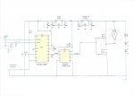
60A  PMW circuit TL494.jpg
 
Last edited:

Goeytex

Senior Member
@ Mejlby

Hi,

The circuit you posted can only drive a motor in one direction. However, the Kart in the video is operating in both forward and reverse. Is this the real circuit or do you have a reverse gear in the Kart?

The L6384 Driver is not typically used used to drive a single direction motor, so I am wondering why you selected this driver.

The Picaxe Basic PWM code is rather straight forward. The center tap of a pot connects to an ADC pin. The Picaxe reads the ADC value with READADC. This value is then scaled ( if necessary) and passed on to the PWMDUTY command.

But before I waste your time and mine on code and circuit diagrams you need to clarify a couple of things.

1. Why did you select the L6384 Driver instead of a single output low side driver?
2. Will the motor need to reverse directions?
3. What Picaxe Chip or Picaxe board you have? Do you have one at all yet?
4. Have you downloaded the Picaxe Software and read through the manuals? (Manual 2 has the command reference.)
5. If yes to #5. Have you tried to write any code and test it in the simulator or on a Picaxe Chip?
6. Do you have a scope or a good multimeter?
 

Mejlby

Member
Hi Goeytex

NO it is no really the engine can run only one direction. I use a 70A relay to switch forward and reverse and it works fine . I have make so it can only change when there is less than 2 V on

I made a controller with TL494 and use L6384 which operates because high Mosfet work much better instead of a diode . The controller can handle 50A without resulting heat in the Mosfet

The reason I want to try a Piaxe IC is that the TL494 can only regulate duty cycle from 0 to 94% and that means that I can not stop the engine completely with the Mosfet driver

No - at first I want to use the relay to forward and reverse

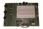
Yes - I have a Piaxe board - see attached

Yes , I have a good and expensive multi-meter that can measure many things and also capacitors. I also have a 50Mz oscilloscope and very fine Laboratory power supply

Yes - I have you tried to write some code and test it in the simulator or on a PICAXE chip . I have make different things - among others incubators to hatch eggs for chickens. The machine regulated how many times per hour the eggs had to be turned and make the right temperature. It works fine. I have mostly worked with analog circuit - and 'm no good to programere Piaxe IC

I would be very grateful if you would help me with code for PWM controller based on a Piaxe 18m2 - ( the ones I have some of)
Piaxe board.jpg

Best regard
Tonny - Denmark
 

Bill.b

Senior Member
The code from the link in #4 is for an 08m.

This code will be ok for the 18M2, the only change required is the ouput from (Pwmout 2, 250, W1 to Pwmout B.3, 250, W1)

The 18M2 had two defined PWM outputs, B.3 (physical pin 9) and B.6 (physical pin 12), you could use either.

Code:
''''''''''''''''''''''''''''
'PICAXE-18N2 E-SCOOTER CODE '
'       21-6-09            '
''''''''''''''''''''''''''''

FirstPowerUp:                                    'This is so the scooter doesn't bolt from under you if the throttle is
Gosub ReadThrottle                               'on when powering up!
If W1 > 100 then Goto FirstPowerUp

Chopper:                                          
Gosub ReadThrottle                               'Reads the Hall Effect throttle value. (0 - 1023 in theory! More like 15 to 995) 
If W1 < 25 then Gosub ZeroThrottle               'Zero out the throttle value if it's already a very low value. 
Pwmout B.3, 250, W1                                'This is where it all happens. 
Poke $12, $06                                    'Pokes the TCON register to prescale the PWN by 16:1 ratio. Now pulses down to 250Hz.
Goto Chopper 

ReadThrottle:
Readadc10 1, W1                                  'Read the throttle value and put it into word varible "W1"
W1 = W1 - 20                                     'Trying to scale the throttle as these Hall Effect throttles are not perfect!
W1 = W1 * 20/19
If W1 > 1023 then Gosub MaxThrottle              'Hold the value to 1023 if it goes over 1023.  
Return

ZeroThrottle:                                    'Zero out the throttle value to zero.
W1 = 0
Return

MaxThrottle:                                     'Maximin throttle value to be held at 1023.
W1 = 1023
Return
Bill
 

Goeytex

Senior Member
Attached is a modified circuit that replaces the TL494 with a Picaxe 18M2. I show a TC4422A MOSFET Driver. It will work great. However, you can use whatever driver you want. I have my doubts about the L6384 because of its low drive current capability. The TC4422A will switch the MOSFETS faster than the L6384.

Below is some suggested some code. It will control the PWM from 0 to 100 percent duty @ 980 Hz. I added code for a safety provision. A switch was added to kill the PWM/Motor if it opens. This can be a tether type as used by Kart racers or a seat switch as used in Riding Mowers. If the driver falls off, the motor stops.

Code:
#Picaxe 18M2
#No_data

setfreq M4

low B.6    '// B.6 will return LOW if PWM is turned OFF 
 
symbol safety_switch = PinB.3
symbol adc_pin = B.1
symbol pwm_pin = B.6

symbol PWM_Val = W1   '// Where 0 to 1020 = 0 to 100 percent duty 


MAIN:
   
   Do while safety_switch = 1           '// Wait for tether/ safety  switch to close
   loop


RUN_:

	pwmout pwmdiv4, pwm_pin, 254, 0    '// Enable PWM @ 980 Hz /  Duty = 0   	
   	
   	Do while safety_switch = 0               '// Run until tether/safety switch is pulled out

		readadc10 adc_pin,PWM_Val    
    	        pwmduty pwm_pin, PWM_Val

	loop	

	pwmout PWM_pin,OFF        '// Kill pwm
	low PWM_pin                    '// Make sure pwm Pin is LOW  

goto main:
 

Attachments

Last edited:

grim_reaper

Senior Member
Am I imagining things, or is R2 in the wrong place on that diagram Goeytex?
It should be in-line with the serial input line, not routed to ground?
 

Mejlby

Member
Hi All

Thanks to everyone for all your help

The circuit I want is shown on the attached. The motor controller I use now work very well - I just can not adjust the duty cycle from 0 to 100%

I have previously followed the circuit as shown in the circuit as Goeytex very kindly made &#8203;&#8203;for me. But mosfet becomes so hot that they burn out and after I changed the circuit to the attached so it can handle about 50A without being heat - Mosfet is quite cold. The diode MUR1560 can not handle the induction from the motor when I run at half speed

I am very happy for the code to Piaxce 18m2

When you see what I want - is it possible to use TC4422A as mosfetdriver for high and low side? hi and low side must synkonicering so they do not short-circuit

Does anyone have any suggestions for this ?

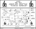
I enclose principle circuit from Q4D

I hope you understand what I mean - I'm not perfect to write in English

Motor controller with to mosfet.jpg

pwm from Q4D.jpg

Tonny
Denmark
 
Last edited:

Goeytex

Senior Member
Hmm,

No, The TC4422 will not drive the high side FET. You will need a bootstrap High Side / Low Side driver for what I think you want. The High side FET needs a Gate to Source Voltage > 24V. But I doubt that using a synchronous high side/ low side driver will solve your heat problem. And besides these cannot operate at 100 percent duty because switching is necessary to refresh the charge pump / bootstrap capacitor.

But I am confused. Which circuit runs cool ? Which circuit runs hot ? Please be specific. Why is it important to operate at 100 percent duty cycle? You will not gain much from 94 to 100 percent.

My guess is that the FETs are heating up due to a poor / inadequate driver setup. The first circuit you posted uses a bipolar totem pole driver. This is not particularly efficient. The 47 ohm gate resistor also slows the ON switching rise time while the diode speeds up the fall time. However, when driving inductive loads we don't always always want super fast rise & fall times as this can induce excessive noise. Sometimes there are trade offs.

Seems to be a bit of a language barrier here, or you are giving information in small bits. You did not previously say that the FETS were getting too hot with the first circuit. We need to know "everything" you can tell us, or we are guessing.

1. How much current does the motor draw when full on ? 20 Amps ? 50 amps? , ??? We need to know this.
2. What components in what circuit are getting hot ? .
3. Which circuit runs cool ? The first one, or the 4QD circuit?
4. If you have a circuit that runs cool at 94 percent duty, why is it so important to have it run at 100 percent ?
 

Mejlby

Member
Hi again Goeytex


First of all i will say thanks for all your help - I am very grateful

I'll try to explain everything.

The first circuit with TL494 and diode across the motor (MUR 1560) was very bad. Mosfet was so hot that they burned out.

then I made a circuit like 4QD but use the TL494 and used a L6384 driver with bootstrap and everything is perfect. I can draw 50A on full speed and mosfet are not hot - they are completely cool and without heatsink. high side mosfet replaces diode MUR 1560 in a much better way

Another advantage is that the motor has regenerative braking which means that when I shut Down, the motor brake. (it's smart when driving downhill - and it works really well)

But but but ..... the problem with TL494 are the duty cycle is only 0 - 96% - which means that when the potentiometer is turned off, the motor will not stop completely - it draws a little bit - because the 4% still run the motor . The reason is that the PWM signal is inverted on low side through the L6384 driver. this is the only problem with the l6384 driver

All this is the reason why I need a PWM signal with a duty cycle of 0 - 100% so that the motor stop completely

when I have solved this problem - I will find a solution to replace the relay with an H-bridge to drive forward and reverse - it's a better option than using a relay

I hope I have explained it well enough

Tonny
Denmark
 
Last edited:

rossko57

Senior Member
All this is the reason why I need a PWM signal with a duty cycle of 0 - 100% so that the motor stop completely
For a STOP condition, just turn the PWM off altogether.
Or, as you are looking to use forward and reverse signals, disable the PWM or disable the driver when neither forward or reverse are true.
 

Goeytex

Senior Member
Since the motor won't completey stop, what you really mean is that the PWM duty cycle to the motor never goes to 0 percent. The PWM range is therefore 4 percent to 100 percent. Not 0 to 96 percent. WE only really care about the duty cycle at the motor.

There are several options.

First Option:
Step 1. Invert the PWM signal coming from the PWM controller chip.
Step 2. Swap the V+ & GND Pins at the POT.
This will give from 0 percent duty cycle (AT THE MOTOR) to 96 percent ( almost full speed)

The PWM controller is now sending an inverted signal. So "OFF" is high and ON is low. If this can be sorted out you won't have to change the controller.


Option 2:

1. Replace the PWM controller with a Picaxe and use the correct polarity PWM/HPWM for the rest of the circuit.

Before I can help any further, I need to see YOUR ACTUAL WORKING SCHEMATIC. Not the one from 4QD or one that you are not really using. If I understand correctly you are now using a circuit similar to the 4QD circuit but have added an L6384 driver.
This is the circuit I need to see.
 
Last edited:

Mejlby

Member
Hi

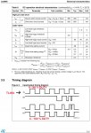
Here you see the ACTUAL WORKING SCHEMATIC I use - and at the same time you can see datacheet L6384

On datacheet I show how the PWM signal becomes Invert

it works really well apart from the motor does not turn off completely
I can draw 50A on full speed and the Mosfet are not hot - they are completely cool and without heatsink

I can not swap the V + and GND Pins at the POT. I have tried. it only means that I have to turn the potentiometer the other way when I want to stop the motor

YES - I think the solution is too Invert the PWM signal coming from the PWM controller chip TL494.

How can I do this?

60A PWM CONTROLLER.jpgDATASHEET L8384.jpg


Tonny
Denmark
 
Last edited:

MartinM57

Moderator
Slightly off topic...I'm not into PWM motor control at all...just an interested observer...

1) you seem to be using the two high side MOSFETs to replace the normal catch diode across the motor - is that a standard design pattern, or something you have come up with?

2) why two MOSFETs in series on the high and low side? I might understand if they were in parallel, but what's the design benefit from having them in series?

3) you talk about using a 70A relay to switch motor direction - so the schematic you show around the motor area isn't actually what you have?
 

Dippy

Moderator
Yes, I agree with Martin... looks odd...even more clarification is needed.

Personally at a 12V supply I would consider using P-chan for the high side. Both MOSFETs could then be driven using standard non-bootstrap drivers. The OP will have to calculate the peak Amps required (easy). For lower power full-bridge drives a chip like (as in 'principle') the TC4469 could save a lot of hassle, though I'm sure the OP will have done the calcs. to see what is suitable.
This should be an easy job but is being made difficult so I'll run away now.
 

Mejlby

Member
hi MartinM57

1) No it's not something I made up. It's such Q4D make their controller.
the advantage is that the engine braking when you shut down the speed

2) Because the controller can handle larger Amps - Sorry - my circuit is wrong - the 2 X Mosfet is not in series but parallel

3) You're right - I have not shown how I turn power to the motor. I use a 6 pole relay where I can turn the power from minus to plus and plus to minus to the motor.

I made the relay so that it can only change when the power to the motor is below 2V - in this way you not destroys motor or controller

60A PWM CONTROLLER-A.jpg
 
Last edited:

Mejlby

Member
Hi Dippy

I'm sorry, I'm not so good - but I would very much learn more - maybe from you !!

What do you mean by a 12V supply ? - it is 24V
 
Last edited:

MartinM57

Moderator
1) but you get "engine braking" every time the PWM signal is at its "off" level during normal control - so with PWM at 50%, then you are getting "engine braking" for 50% of the time. How does that affect overall efficiency - I would have thought that you would want "engine coasting" in this period?

2) OK :)

3) getting more off topic, how do you measure/only switch the relay "when the power to the motor is below 2V"?

(I suspect you didn't expect the "Spanish Inquisition" (as in Monty Python) when you posted this thread :D)
 

Mejlby

Member
1) The first circuit I made with a diode across the motor did NOT braking. The circuit I have attached brakes the motor. You can read more about this on Q4D website.

3) I measure the voltage across the potentiometer and uses an LM324


"I suspect you did not expect the" Spanish Inquisition "(as in Monty Python) vhen you posted this thread" ...... I'm sorry I do not know what you mean???
 

Goeytex

Senior Member
The TL494 has several output options since the output transistors are uncommitted. The attached diagram shows the internal output stage of the TL494 with two drive options. Figure 1 shows your existing configuration. Figure 2 shows how to invert the PWM out signal.

Change the TL494 drive configuration to that shown Figure 2. Then reverse the connections to the pot.
 

Attachments

Mejlby

Member
Hi Goeytex

You are just amazing .... it's a very easy solution ... many many thanks for your advice. This I will try today. (It's weekend ... nice :D)

Do you agree with what I write about braking? (That's the experience I have done)
 

MartinM57

Moderator
"I suspect you did not expect the" Spanish Inquisition "(as in Monty Python) vhen you posted this thread" ...... I'm sorry I do not know what you mean???
1. A famous comedy sketch from the 1970's British TV comedy called Monty Python, and
2. ...as in the thing that happens when you ask a simple question and get more and more ridiculous off topic and difficult questions in return :)
 

Mejlby

Member
ha ha ha .... now I understand - i know the sketch with Monty Pyton ...very funny

Yes .... I am only amateur and so it can be difficult to respond to all .......AND I have to read and reply in English ..... why write all not in Danish .... hahaha
 

Goeytex

Senior Member
Hi Goeytex

Do you agree with what I write about braking? (That's the experience I have done)
I am agnostic on that. I would probably need to study for months or longer to get up to speed on modern motor control. Regenerative braking, battery charging, etc. This stuff is not trivial if you want efficiency and reliability. There seems to be a lot of black magic involved.

Motor control is not really my cup of tea. I did SMPS design for quite a few years while avoiding any assignments that included motors as much as possible. I have a bit of (long past) experience with the TL494 since that is one of the old bones I cut my teeth on back in the 80's.
 
Top