lbenson
Senior Member
Following up on Dr_Acula's recent revelation (to me), in his PCB example, that the 14M can do multiple ADCs, I tried to code up an example in the simulator. Manual 1, p. 70-71 shows that legs 7, 8, 9, and 10 can be [ADC0, ADC1, ADC2, and ADC3 respectively--oops, I'm wrong--should be] ADC0, ADC3, ADC2, ACD1 respectively, but for ADC1-3 only after their respective pins have been set to inputs. Neither this section nor the READADC command section makes clear the syntax for using these, but I experimented in the simulator until I got something which produced no syntax errors. The code is as follows:
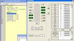
When I run the simulator, I get only ADC adjustment controls labelled "A0" and "A4". When I set them to, for example, "25" and "45" respectively, I get "25" in b1 and "45" in b2, indicating that my "readadc 1,b1" and "readadc 2, b2" were connected to the controls in the simulator. Have I got the syntax entirely wrong, or is there a problem with the simulator? And if the syntax is right, shouldn't the simulator present adjusting controls for each input?
I can also add the following adc commands--which should be illegal--and they compile and run, putting "25" in b5 and b9.:
I don't have the necessary parts with me to test this on an actual chip.
Code:
'14ADC
#picaxe 14M
let dirsc = %110000 ' C0-3 as inputs (for ADC), C4-5 outputs
main:
pause 5000
readadc 0,b0
readadc 1,b1
readadc 2,b2
readadc 3,b3
goto mainI can also add the following adc commands--which should be illegal--and they compile and run, putting "25" in b5 and b9.:
Code:
readadc 5,b5
readadc 8,b8
readadc 9,b9Attachments
-
 69.5 KB Views: 26
Last edited: