Greetings:
Summary:
On an AXE091 a 20X2 ADC reading is taken from a backup battery for a DS3231. With the 5V P/S off, the battery appears to “back feed” into the entire circuit, surely draining the battery.
The battery (without the diode shown in the schematic) pegs the ADC at 1023, so a divider is needed. Makes sense.
But how is the power getting back into the circuit as a whole?
The PIC18(L)F1XK22 datasheet states: Max ADC impedance is 10K.
I'm a novice and do not understand how voltage relates to impedance with regard to a power source. Perhaps a better understanding of Ohm's law is in order.
In any case, is the 10K max relevant to the issue?
The associated forum URLs are at the bottom of this post.
Thanks in advance,
Terry
[HR][/HR]
Detail
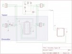
The attached shows 3 schematics
1/ MaceTech’s ChronoDot that uses the DS3231
2/ A “Topper” board holds a backup battery and sits directly on the ChronoDot
3/ A 20x2 which is placed in an AXE091 (no prog or decouples shown)
Battery: Panasonic CR-2477 / 3V – 1000mAh
The code referring to ADC is:
And later
The complete code is found as an attachment
The problem is with the ADC connection to the 20X2.
With the AXE091 P/S off, and the ChronoDot’s “BAT” connected to pinC.3 of the 20X2, a small amount of power remains as evidenced by the AXE091’s power LED. The terminal continues to function showing the correct time, any alarms and the ADC reading. Even with the terminal closed, programming is disallowed.
Obviously, this will drain the battery. Removing the ADC connection solves the problem but defeats the whole idea.
Using the 1st diode found in a parts drawer (an IN4001), the problem is solved. The orientation has been double checked per the schematic. The diode’s band faces the BAT.
But this is a cheap fix, and I didn’t learn anything.
So with a 1023 reading, the battery is blasting the ADC
That observation, the extracts and forum references below suggest a voltage divider.
The IN4001 has ~ .7 voltage drop.
Is this the correct solution?
[HR][/HR]
Background
PIC18(L)F1XK22 Datasheet / Page 213
For the ADC to meet its specified accuracy, the charge
holding capacitor (CHOLD) must be allowed to fully
charge to the input channel voltage level.
The maximum recommended impedance for analog
sources is 10 k.
Picaxe Manual 2 / Page 32
The default Vref +signal is the power supply (V+) and Vref- signal is 0V, so the
analogue voltage range is the same as the power supply to the PICAXE chip.
http://www.picaxeforum.co.uk/showthread.php?4852-08M-ADC-Input-impedence&highlight=ADC+leakage
http://www.picaxeforum.co.uk/showthread.php?13524-Making-best-used-of-ADC-resolution-for-reading-battery-voltage&highlight=ADC+leakage
Summary:
On an AXE091 a 20X2 ADC reading is taken from a backup battery for a DS3231. With the 5V P/S off, the battery appears to “back feed” into the entire circuit, surely draining the battery.
The battery (without the diode shown in the schematic) pegs the ADC at 1023, so a divider is needed. Makes sense.
But how is the power getting back into the circuit as a whole?
The PIC18(L)F1XK22 datasheet states: Max ADC impedance is 10K.
I'm a novice and do not understand how voltage relates to impedance with regard to a power source. Perhaps a better understanding of Ohm's law is in order.
In any case, is the 10K max relevant to the issue?
The associated forum URLs are at the bottom of this post.
Thanks in advance,
Terry
[HR][/HR]
Detail
The attached shows 3 schematics
1/ MaceTech’s ChronoDot that uses the DS3231
2/ A “Topper” board holds a backup battery and sits directly on the ChronoDot
3/ A 20x2 which is placed in an AXE091 (no prog or decouples shown)
Battery: Panasonic CR-2477 / 3V – 1000mAh
The code referring to ADC is:
Code:
Let ADCSetup = %0000000000001000 'ADC3
Code:
BatteryCheck:
    Readadc10 3,BatteryADC        'Read ADC3 into VAR "BatteryADC"
                        'Per the manual
‘On X2 parts you must use the ADC channel, not the pin ‘number, in the readadc
                        'command (e.g. readadc10 0,w1 NOT readadc10 A.0, w1)

    Sertxd ("Battery ADC :",#BatteryADC,CR,LF)
        If BatteryADC < 450 Then Toggle BattLowLED    'See Scratchpad for ADC-Volts table
            EndIf                        'Min Battery Spec is 2.3V
        If BatteryADC > 450 Then Low BattLowLED
            EndIf
    Return
The problem is with the ADC connection to the 20X2.
With the AXE091 P/S off, and the ChronoDot’s “BAT” connected to pinC.3 of the 20X2, a small amount of power remains as evidenced by the AXE091’s power LED. The terminal continues to function showing the correct time, any alarms and the ADC reading. Even with the terminal closed, programming is disallowed.
Obviously, this will drain the battery. Removing the ADC connection solves the problem but defeats the whole idea.
Using the 1st diode found in a parts drawer (an IN4001), the problem is solved. The orientation has been double checked per the schematic. The diode’s band faces the BAT.
But this is a cheap fix, and I didn’t learn anything.
| Voltage Measurements | 5V PowerOn | 5V PowerOff |
| ChronDot BAT | 3.17V | 3.17V |
| 20X2 pinC.3 | 110mv | 68mv |
| ADC Measurements | 5V PowerOn | 5V PowerOff |
| With Diode | ~501 | No Terminal |
| Without Diode | 707 | 1023 (Term runs on BAT) |
So with a 1023 reading, the battery is blasting the ADC
That observation, the extracts and forum references below suggest a voltage divider.
The IN4001 has ~ .7 voltage drop.
Is this the correct solution?
[HR][/HR]
Background
PIC18(L)F1XK22 Datasheet / Page 213
For the ADC to meet its specified accuracy, the charge
holding capacitor (CHOLD) must be allowed to fully
charge to the input channel voltage level.
The maximum recommended impedance for analog
sources is 10 k.
Picaxe Manual 2 / Page 32
The default Vref +signal is the power supply (V+) and Vref- signal is 0V, so the
analogue voltage range is the same as the power supply to the PICAXE chip.
http://www.picaxeforum.co.uk/showthread.php?4852-08M-ADC-Input-impedence&highlight=ADC+leakage
http://www.picaxeforum.co.uk/showthread.php?13524-Making-best-used-of-ADC-resolution-for-reading-battery-voltage&highlight=ADC+leakage
Attachments
-
64.5 KB Views: 9
-
 356.3 KB Views: 24
Last edited: