ACS750 to PICAXE, has anyone done it with 24 volts

D n T

Senior Member
I'm trying to monitor 24 volts between nil draw and up to 50 amps and I want to use the Allegro ACS 750

According to the many hours of surfing on the subject, It should wire straight in to the ADC input with a tant capacitor as a filter.
I would like some one to confirm this because in order to test the ACS750 at more than a couple of amps I have to wire it in and go for a drive. My bench power supply can do upto 5 amps but thats it.

BEFORE ANYONE HAS A STRESS AND WARNS ME ABOUT USING PICAXE IN A CRITICAL SYSTEM, It is in an electric scooter and if it fails I will just walk home pushing it, its not a critical, or even required sytem and the only problem it is liable to cause is the accelerated rate at which my hair is disappearing.

I think I might have to build a "dyno" to test it in the shed, does that mean it will be FULLY SIK because I have run it on a dyno?? Thats what the local hoons seem to think...
 

moxhamj

New Member
It should work fine. It looks like it gives an output in volts and if the supply volts to the allegro are 5V then there is no output it could give that would upset a picaxe. Filtering may or may not be needed buy you could start with 0.1uF and 10k. 10k between the allegro and the picaxe, and the cap between the picaxe pin and ground. Try it on the bench at 5A and you should get an ADC value of 10x that at 50A.

That is a pretty powerful scooter - over 1000W. I've got a 100W one that can get up to 30Kph on the flat so yours should be burning rubber...
 

D n T

Senior Member
The scooter??

The scooter is more like an Electric Vehicle, my students "design and build" them each year and then they test and race them. We have 2 x 18 Ah batteries and a 200- 250 watt motor, we race for an hour and do an max speed of about 35 Km/h, which, when your backside is about a coke can off the ground, seems REAL fast!!
I'm addicted to it and build my own for the open class every year, I'll try and attach a photo or 2... I looked and will have to look again, look for further postings.
By the way, I won't use 1000 watts but its good to have a little bit of room to expand.
I think that running a 24 volt motor, the maths goes a bit like this...
motor wattage: W = V x A
W = 24 x 18
W = 432
Assuming no losses, etc, etc.
We have use 200W, 250W, 400W and 500W.
The 400W and 500W both die before an hour is up.
The 250W runs well if the driver isn't a rev head.

I have to go find a picture to post here
By the if you are from SW Western Australia and want to know a bit more, post.
 

animal2

New Member
Miniumum output Resistance = 10k
Maximum output drive capacitance=10nf
DC Offset =.6v
.06v per amp output
I am using an ACS-755-050
unipolar
If you use a capacitance higher than 10nf the output oscillates,have alook with a cro.
Noise level of ACS755 is a bit of a problem for low readings i find,
i have offset picaxe to read above 1.5 amps (below 1.5 amps reading jumps +/-.7 amps) and this seems to be fine and pretty accurate to .2 amps from 1.5 - 50 amps
I will try opamp filter/amp soon, will let you Know results
 

profmason

Member
To piggyback on this thread, I have been working on a solar panel monitoring project for quite a while. The panel produces up to about 24 volts with a peak of around 3.5 amps. (Measured by analog meters at the panel.) I have been using a MAX471 to measure the current of the panel, with limited success. (OK, I had reasonable success on the bench, but the students had no luck at the array.) Here is my writeup on using the MAX471 with the picaxe.
http://profmason.com/?p=386

Can anyone suggest another current sensor that gives a nice voltage output proportional to current that works up to about 5 Amps?

Any details on why the ADC input needs to have a capacitor across it?

Thanks!
 

D n T

Senior Member
Att profmason have a look at this

Have a look at this PDF, Ive got dial up so it took a while to down load.
The interesting bits start on page 28, you might even see components you already know about, but the diagrams and some explaination are all there.

http://www.hirstbrook.com/uc/LEC15 PIC AD.pdf

This is not a hot link, you will have to cut and paste, sorry.
 

premelec

Senior Member
For high side current monitor look at Zetex.com [e.g. ZXCT1010] but note that these inexpensive current to proportional current to ground [neg] units are only good to 20VDC - however you can use a zener between the IC and sense resistor to keep within ratings [say 12v zener].

Otherwise look at Allegro Microsystems units which are Hall effect and isolated.

You can fashion your own circuit using a sense resistor and two identical voltage dividers from the high side to ground which then fed into an operational amplifier referenced to low side with whatever gain you require...
 

moxhamj

New Member
Re Premelec, I'd have done it that way too using a current sense resistor and a differential op amp (+/- gain). It is a simple solution with one chip and I've certainly used it for currents up to 10A. However, some quick back of envelope calcs - say you only want to lose 1W in the sense resistor and say the amps are 50 then W=I^2R so 1=50^2R so R =1/250th of an ohm. I'm sure there is a bit of wire with that resistance but it would take some experimentation to calibrate. There may even be a wire to the motor that happens to have resistance of around this value and you could just measure the voltage drop (as long as all the connctions are soldered and the resistance stays constant). It would be simple to test - run the motor at full load (up a hill) and measure volts/milivolts on a DMM across one of the wires going to the motor.
 
Last edited:

hippy

Ex-Staff (retired)
BEFORE ANYONE HAS A STRESS AND WARNS ME ABOUT USING PICAXE IN A CRITICAL SYSTEM, It is in an electric scooter and if it fails I will just walk home pushing it
Assuming failure mode isn't that it blows both your legs off.

Only joking :) :) :) :)

The main thing is knowing when something is or isn't safety critical and more generally the consequences involved. You seem to have it well under control.
 

profmason

Member
This thread revived my interest in an old project. I spent the day fighting with the MAX471.
When I initially fed the output of the 471 to the picaxe ADC, I got a series of oscillating values that increased with current.

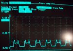
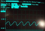
Hmmm. I put the output on the scope and saw that the MAX471 outputs a series of pulses with the amplitude proportional to the input current. Unfortunately, these pulses are so slow that the readADC command was sampling at different points in the output wave. I spent some time with capacitive solutions (needed anyway to clean up the waveform) I started thinking about building a hardware integrator. (Those are memories from way back!) Then I thought, why not just average 100 ADC values. That would sample several periods of the wave and should give me a decent result. (It does, but requires about 20 ms of processing time (Which is no big deal))
Code:
'Read a MAX471 Current sensor for output currents between 0.2 and 3 amps. 

symbol counter = b3
main:
	w0 = 0
	'Read the ADC 100 times and accumulate the value
	for counter = 1 to 100
		readadc 0,b2
		w0 = w0 + b2
		next counter
	'Find the average of the ADC reads
	w0 = w0 / counter
	'Output current in mA = 20.33 * w0 - 336
	w2 = w0 * 20
	w2 = w0 / 3  + w2 - 336
	sertxd (#w0,",",#w2,13,10)
goto main
If you folks will take a look at the attached waveforms and give me any superior strategies for getting the peak pulse amplitude. Is there something real obvious I am missing?

Anyway, the MAX471 is a pretty good solution for measuring currents in the range between 0.2 and 3 amps.
Here is a link to my project notes:
http://profmason.com/?p=517
 

Attachments

moxhamj

New Member
What an odd output? From the cro timebase of 50us I take it these are very fast pulses so would a low pass RC filter with a time constant of 1/100 second (or more) work? What was the 'capacitive solution' schematic?
 

profmason

Member
Unfortunately, the pulses aren't that fast! That 50us is not the time per division but the time for 1 sample on the scope! These pulses are VERY slow ie about 200 hz. Thus the problem with using a capacitor. I tried using a RC circuit with different time constants between 1/10th of a second to 1/1000 of a second.

Thanks for the help folks! The students are fighting with it now. They still need to get it integrated with the rest of the data acquisition system. We had 3 days of torrential rain (For Southern California that means 3 inches). The data acquisition system survived in its tub on the roof and kept perking along through lighting etc.

have fun!
 

moxhamj

New Member
I wonder if a peak level detector would work? Ie a 914 diode into a capacitor and read with ADC. Then after reading the value, reset (discharge the cap) by making the pin an output and making it low.
 

D n T

Senior Member
I got a linear, almost, progression, most stoked

I've finally been above to test it on my "dyno".
The ADC10 results when compared to my particulary accurate ( for this anyway) DMM have a linear relationship, OK thats that part of my R+D done, now to put into my cocktail of code

Thanks to all those who helped and also go to DAVID LINCOLN for his help in this.

By the way, a photo of the vehicles we raced two years ago, the vehicle on the right is the one I used to dyno and the black hat bent over it is self
 

Attachments

premelec

Senior Member
I just noticed a warning about using high side current monitor ICs where the common mode rating of the OPamp monitoring the sense resistor may be out of limits when a short circuit happens thus giving false current readings... www.edn.com/080110toc1-
worth noting...
 
Top