I'm trying to run the picaxe and a camera from the same 3 V battery. Even the so-called logic level mosfets won't work down that low.
The datasheets claim the LL mosfet will work down to 2 volts, and they will, sort of, but if you read the datasheet that 2 volt specification is only guaranteed at whopping drain current of 250 microamperes and 25 degrees C. Look at the graph and you find the 2 volts is up to 2.5 volts at 250 milliamps and 2.75 volts at one amp!
The 'axe output voltage with 3 volts in is 2.3 volts. Even the logic level device won't work. The load itself can be finicky too. My camera checks the battery voltage before it agrees to come on. If the turn on isn't sharp enough it senses a low battery condition and refuses to initialize. (there's another gotcha in the datasheet called threshold pulse response or something like that)
My design goal is reliable operation down to 2.7 volts from 3V alkaline batteries from 0 C to 50 C temp.
The solution is to generate a separate bias power source to turn on the power mosfet. I tried a voltage multiplier using the PWM output. That proved unwieldy because it took a lot of stages and each stage takes a hit from the forward voltage drop of the diodes used. Getting a solid ten volts out took 20 stages of multiplication.
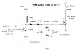
Using the pwm to switch an inductor turned out to be a bulletproof way to get good solid bias supply. With 10 volts nearly any mosfet will switch fast are reliably. (the bias circuit itself can generate up to about 80 volts with the right component selection, and no loading)

I'm driving it with a pulse train of 40 KHZ with a 10% duty cycle (10% high 90% low). None of the component values are all that critical. It works well with a 10 KHZ 50% duty on up, but high speed, low duty cycle, keeps the power dissipation low. It uses about 30 - 40 milliwatts of power. Including what the axe supplies to drive it. If the 1 K is raised to about 20 K it can run as low as 5 milliwatts. The inductor is a 3 mhy type, but 1-3 mhy is fine, or 30 turns of magnet wire on a ferrite core or bead works well. The 220 K on the output is to give the mosfet a discharge path. The 3 Vz diode is only there so the mosfet won't turn on and stay on with a higher supply voltage (like 4.5). The 8 volt zener and LED keep the voltage limited to ~10 volts, and give a visual indication that it works.
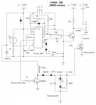
A second seperate source can also be derived from the same inductor with the duplicate addition of everything west of the inductor. It can also be used as a negative supply by changing the rectifier around and leaving out the 3 Vz and switching the polarity of the output limiter. (you may have to tweak it a little since I didn't really spend time with it, just verified it would work). It can also be used as an isolated supply by winding a core or bead with two 30 turn windings and moving the limiter section to the isolated output winding. - For a high-side switch N channel mosfet switch.
This is the test program I'm using to run it with the 14M
Pin means "leg" in 'axespeak - the physical I.C. pin, not the logical I/O number
The datasheets claim the LL mosfet will work down to 2 volts, and they will, sort of, but if you read the datasheet that 2 volt specification is only guaranteed at whopping drain current of 250 microamperes and 25 degrees C. Look at the graph and you find the 2 volts is up to 2.5 volts at 250 milliamps and 2.75 volts at one amp!
The 'axe output voltage with 3 volts in is 2.3 volts. Even the logic level device won't work. The load itself can be finicky too. My camera checks the battery voltage before it agrees to come on. If the turn on isn't sharp enough it senses a low battery condition and refuses to initialize. (there's another gotcha in the datasheet called threshold pulse response or something like that)
My design goal is reliable operation down to 2.7 volts from 3V alkaline batteries from 0 C to 50 C temp.
The solution is to generate a separate bias power source to turn on the power mosfet. I tried a voltage multiplier using the PWM output. That proved unwieldy because it took a lot of stages and each stage takes a hit from the forward voltage drop of the diodes used. Getting a solid ten volts out took 20 stages of multiplication.
Using the pwm to switch an inductor turned out to be a bulletproof way to get good solid bias supply. With 10 volts nearly any mosfet will switch fast are reliably. (the bias circuit itself can generate up to about 80 volts with the right component selection, and no loading)
I'm driving it with a pulse train of 40 KHZ with a 10% duty cycle (10% high 90% low). None of the component values are all that critical. It works well with a 10 KHZ 50% duty on up, but high speed, low duty cycle, keeps the power dissipation low. It uses about 30 - 40 milliwatts of power. Including what the axe supplies to drive it. If the 1 K is raised to about 20 K it can run as low as 5 milliwatts. The inductor is a 3 mhy type, but 1-3 mhy is fine, or 30 turns of magnet wire on a ferrite core or bead works well. The 220 K on the output is to give the mosfet a discharge path. The 3 Vz diode is only there so the mosfet won't turn on and stay on with a higher supply voltage (like 4.5). The 8 volt zener and LED keep the voltage limited to ~10 volts, and give a visual indication that it works.
A second seperate source can also be derived from the same inductor with the duplicate addition of everything west of the inductor. It can also be used as a negative supply by changing the rectifier around and leaving out the 3 Vz and switching the polarity of the output limiter. (you may have to tweak it a little since I didn't really spend time with it, just verified it would work). It can also be used as an isolated supply by winding a core or bead with two 30 turn windings and moving the limiter section to the isolated output winding. - For a high-side switch N channel mosfet switch.
This is the test program I'm using to run it with the 14M
Code:
'10 V power supply transistor driver W/10% duty cycle
'picaxe 14M

start:
	pause 100
	pwmout 2,24,10	'generate 40khz pulse train on pin5 (pwm2)
	pause 500 		'wait half a second
	pwmout 2,0,0 	'turn off pulse train on pin 5
	low portc 5		'make pin 5 low
	pause 500		'wait half a second
	goto start		'repeat forever