D
Deleted member 67719
Guest
Here's the basic concept of my project:
It is going to be a system which will be placed in a garage - it will warn the driver if the car is getting too close to the wall.
Inputs: Ultrasonic range sensor
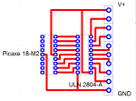
Process: Picaxe 20 M2 or X2 (Please advise me to which chip I should use)
Darlington Driver (ULN2003A)
Outputs: Serial LCD Module
Ultra-bright LEDs
Buzzer
Sidenotes: I may also buy the bracket/mount for the ultrasonic range sensor and/or the GBX013 miniature servos.
If I wanted to take it further - I'm going to use an infrared receiver so it can be switched on remotely.
My main question is - which Picaxe chip will be best for this project? What would you change about this project? Is it overly complicated (i'm totally fine with it being complicated)?
Also I want to state that this is just a school project and it is meant as a usable model. I have access to an laser cutter and PCB cutter.
Finally I will explain this project in more detail:
As the driver pulls into the garage the system will turn on. The LCD display will show the distance that the car is from the sensor/wall. On each side of the product there will be a set of 4 Ultra bright LEDs as the car gets closer the LEDs will flash faster. Before the car hits the wall.. the buzzer will sound.
It is going to be a system which will be placed in a garage - it will warn the driver if the car is getting too close to the wall.
Inputs: Ultrasonic range sensor
Process: Picaxe 20 M2 or X2 (Please advise me to which chip I should use)
Darlington Driver (ULN2003A)
Outputs: Serial LCD Module
Ultra-bright LEDs
Buzzer
Sidenotes: I may also buy the bracket/mount for the ultrasonic range sensor and/or the GBX013 miniature servos.
If I wanted to take it further - I'm going to use an infrared receiver so it can be switched on remotely.
My main question is - which Picaxe chip will be best for this project? What would you change about this project? Is it overly complicated (i'm totally fine with it being complicated)?
Also I want to state that this is just a school project and it is meant as a usable model. I have access to an laser cutter and PCB cutter.
Finally I will explain this project in more detail:
As the driver pulls into the garage the system will turn on. The LCD display will show the distance that the car is from the sensor/wall. On each side of the product there will be a set of 4 Ultra bright LEDs as the car gets closer the LEDs will flash faster. Before the car hits the wall.. the buzzer will sound.
")