A 5v to 3.3v interface update

cvrwy

Member
I have been working on a wireless project that uses the Picaxe 28X1 and an Xbee device. The Picaxe being a 5 volt device and the Xbee a 3.3 volt device leads to interfacing problems. This website recommends using a two resistor voltage divider method of interfacing 3.3 volt and 5 volt devices, but it is uni-directional (operates in one direction only). The PicAxe forums also mentions operating the Picaxe on 3.3 volts, which leads to other problems.

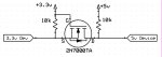
I found a neat circuit that uses two resistors and a Mosfet for a bi-directional interface that has been around for ages it seems. The problem using that circuit is that the Mosfet is in an SOT package and is too small for me to solder reliably. After doing a lot of digging I finally found a Fairchild Mosfet that is in a TO-92 package and easily used in through-hole PCBs as well as conventional breadboards and is available here in the states and might be available across the big waters too. The chip is a 2N7000TA.

Here's the interface that I have been using. It is accurate, reliable and usable for us. I thought that I would pass it on to the group.
 

Attachments

hippy

Ex-Staff (retired)
Staff member
Isn't that a bit overkill ? Unless I've misunderstood the need for such an interface in this case.

Yes, the 5V to 3V interface operates uni-directionionally ( 5V PICAXE output to 3V3 XBee input ) but that's a one way link, nothing comes back up that line to the PICAXE.

Likewise the XBee to PICAXE link doesn't need any level conversion as the PICAXE can read the 3V3 signal as is and will never be sending anything to the XBee via that line.
 

Dippy

Moderator
Why?
I agree with hippy.
I've used PIC@5V --> XBee@3.3 using 2K2/3K3 and 1K8/3K0 level shifting.
And XBee@3.3 ---> PIC@5V direct.

The only potential accicdent (hahaha) i can see is if you got your I/O wrong.
And yes I have had an accident in the past....
 

cvrwy

Member
Joe, I used the free schematic program that is part of the ExpressPCB download that is available to generate schematics and PCB layouts. You can get it here.....http://www.expresspcb.com/ExpressPCBHtm/Free_cad_software.htm

Hippy, I don't feel that adding one more chip to a circuit is over-kill. Yes, is is a one-way interface, but it makes the input from an Xbee "high" a full 5v on my 28X1. I just like the idea that my 5v devices will get a full 5v "high" and my 3.3v devices get their recommended 3.3v "high". It is well worth using the interface.

It certainly eliminates any "accidents".
 
Last edited:

RexLan

Senior Member
You could just as easily use a LP2950 (3.3v regulator) in a TO-92 package off your 5v source and be done with it. 1 part instead of 3. Running off the filtered 5v line you don't need the normal bypass caps.
 

womai

Senior Member
While I'd agree that for downconversion (interfacing 5V --> 3.3V) a voltage divider is the simplest solution, I like the circuit when you have to go the opposite direction.

Another option for upconversion would be to use one of Analog Device's ADUM series devices, for example the ADUM1201 (they have a whole series with different numbers of lines in each direction):

http://www.analog.com/en/interface/digital-isolators/adum1201/products/product.html

They are available in SOIC package which isn't that hard to solder even for a hobbyist.

Wolfgang
 

BeanieBots

Moderator
I'm with Hippy & Dippy on this.
Simple current limit resistor (not even a potential divider) is all that's need for both directions.
 

cvrwy

Member
Excellent choice, Wolfgang.........I can get the ADUM1201 from DigiKey for $3.13 USD. That device can certainly free up a lot of space on the PCB. Got to check it out............Thank you for the info.
 

lbenson

Senior Member
@BB et al
>Simple current limit resistor ... is all that's need for both directions.

22K is used in the programming circuit for RS232 -> 5V picaxe--what R would be suitable for RS232 -> 3V3 (not PICAXE programming)?
 

Dippy

Moderator
Well, I prefer level shifting via pot-div when targetting a device where I don't have a drawing of the input. Not every Data Sheet is as info-rich as Microchip stuff.

Yes, PICs have a little clamping diode which allows careful use of a single suitable resistor, but does every device? Guessing isn't good enough. Too risky. Would you do that with an SD card?

If I don't know then I level-shift. It's safer.

For example, I don't know the guts of an Xbee. So, I play safe - especially as they cost a bit!!

And in the 'other direction' a device giving nominally 3V3 logic will be OK with a PIC/PICAXE TTL input (PICat 5V) with a direct connection, though a resistor could prevent accidents I agree. It would, however, not be good enough (according to Data Sheet) for an ST input. So, on second thoughts and under those circumstances it may/will be necessary to use the shift-up device as mentioned.

I can't answer your question Ibenson. All I can say is that will depend on the actual device. Personally, I'd always play safe, spend the extra penny and do level shifting.
 

womai

Senior Member
Excellent choice, Wolfgang.........I can get the ADUM1201 from DigiKey for $3.13 USD. That device can certainly free up a lot of space on the PCB. Got to check it out............Thank you for the info.
Even better. You can get them as free samples from Analog. Max. 2 devices per type and 2 different types per sample order. If all you are doing is a one-off design, that should have you covered. Shipping is usually within a few days (and it's also free).
 

westaust55

Moderator
I'm with Hippy & Dippy on this.
Simple current limit resistor (not even a potential divider) is all that's need for both directions.
Not XBee related but when I tried a "short-cut" to use a single resistor at a 5V to 3.3V interface it just pushed the supply rail for the 3.3V powered chip up to 5V when any input signal from the PICAXE went high.

Okay another chip, but for genuine bi-directional signal you could consider the 74LVC254 which operates on 3.3V and has 5V tolerant inputs.
 
Last edited:

cvrwy

Member
I tried getting the chips from Analog, no can do. I don't have a "company" email account..........so they say.
 

papaof2

Senior Member
Company email account:
www.mydomain.com with web page.
Your email is myname@mydomain.com

Domain registration is ~$20US/year (can be less)
Web hosting is ~$20US/year (can be less)
Typical hosting accounts allow hundreds of email accounts (maybe unlimited), so you can have
myname@mydomain.com, sales@mydomain.com, support@mydomain.com, etc - and all of them can be forwarded to your regular email address so you only have to check email at one place.

I currently have 3 domains running on cheap hosting (under $20US/year) - including the one that matches the company name on my business license.

John
 

cvrwy

Member
Wolfgang, you are "OK" in my book. A couple of ADuM1201 came in today. Not only was I able to practice soldering an SOIC chip but confirmed that it works very well. Initially it appears that no pull-up resistors are needed. So, I'll be able to remove 4 resistors and 2 MosFets by installing the one 2-channel ADuM1201 on my PCB. Now on to re-designing the board, maybe reducing its size. Again, thank you very much, Wolfgang.
 
Top