8M to ignite glowplugs and sound buzzer to help locate a lost plane

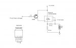
The purpose of this circuit is to ignite the glowplug in an RC airplane and also to sound a buzzer if the transmitter is turned off.
The glow should ignite at about 1/4 throttle (pulses about 100). I am reading the throttle signal in pin3. The trigger point will be set on the workbench using a trim pot and reading ADC on pin 2. Signal from a different channel will be used to fine tune the trigger point (if neccessary) from the transmitter without opening the airplane. If the plane is lost a buzzer will sound when the transmitter is off and the pulses from both channels go to zero.
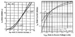
I would appreciate any comments or suggestions regarding the circuit or the code. One of my doubts is the value of the trim pot considering that the voltage is supplied from the 1.2V battery that drives the glow plug. If that voltage is too low, I could use 4.8V from the receiver battery. But in that case I would like to know the current because I am concerned about running out of power for the receiver and servos.
Code:
;    Target PICAXE:8M	
; ******************************* 

'Ports
Symbol Thr=input3
Symbol Adj=input1
Symbol Trm=input2
Symbol Buzz=output2
Symbol Glow=output4

'Variables
Symbol Th=b0
Symbol Ad=b1
Symbol Tr=W1
Th=0
Ad=0
Tr=0
Low Glow
Low Buzz

	Main:
readadc10 2,Tr
pulsin 3,1,Th
pulsin 1,1,Ad
If Th=0 or Ad=0 then goto Alarm
Ad=Ad/4
Tr=Tr/4
Th=Th-Ad
Th=Th-Tr
If Th<100 then goto Ignite
Low Glow
goto Main

	Alarm:

high Buzz
Pause 500
Low Buzz
Pause 100
High Buzz
Pause 500
Low Buzz
Pause 100
High Buzz
Pause 500
Low Buzz
Pause 100
High Buzz
Pause 1500
Low Buzz
Goto Main

Ignite:
High Glow
Goto Main
 

Attachments

toxicmouse

Senior Member
i would be surprised if the 08m drains your 4,8V receiver supply in the few minutes that the plane is airborne, but there is code you could add to reduce the power usage of the 08m, but then you may have problems with the glow plug.

readadc10 is redundant if you are going to divide it by 4, because you will reduce a 10 bit number to an 8 bit number- which is the same as readadc.

if the receiver loses signal then the glowplug will remain on, is this correct? i would have thought you would want it off. also, during flight you may lose signal every now and then, for the alarm it may be better to check that the signal is lost for a few seconds, assume the plane has hit the ground- and then switch off the glow plug and turn on the alarm in a loop and go into low power mode to ensure the buzzer sounds for as long as possible.

good luck
 
Thank you, good catch, if the plane looses signal the glow should be off. I'll make that addition to the code.
I never used adc before, I want the value of readadc to be around 40. With 4.8 volts what should be the value of the resistance in the pot?
 
Last edited:

toxicmouse

Senior Member
i think your question has 2 meanings, so i will answer both:

1-the value of the pot does not matter, but the higher the value the less current will go through it. in your case you want a high value pot to reduce power consumption, although a 10K pot should use less than 1mA at 4,8V, so it should be fine.

2- the resistance to ground needs to be in the region of 1k5 on a 10k pot to get 40/255 reading on readadc (this is the position of the wiper on the pot). the best way to set the pot is to use this:

readadc 2,Tr 'set symbol Tr = b2, rather than w1
sertxd (#b2,cr,lf) 'sends pot reading to the terminal program. hit F8 after the download.

then just adjust the pot to the general region you want it to be at and fine tune on the airfield. be aware that there may be significant problems with pulsin- read the other threads that are currently on the active forum. the glowplug code may have problems, but the buzzer code is very likely to work. this is because if the pulsin reading is 0 then it usually remains there, but if it is in the working region of the RX pulses (80-200 depending on manufacturer) then it may rise and fall significantly. to combat this in your application i would say use loads of hysteresis.
 

Wrenow

Senior Member
I would be careful about using B0 and B1 for throttle and adjustment. I believe Pulsin reads in a Word variable, and B0 and B1, as I recall, are the two halves of W0, correct? You may be getting some unexpected results.

Cheers,

Wreno
 
Thank you Wrenow, you are right, I tried it in a breadboard and was getting bad results. When I changed to word variables it started to work ok.
This forum is great for newbies such as myself.
 
Everything is working EXCEPT.
The desired voltage at the GLowPlug terminal is achieved but the current is 400mA which is not enough to ignite the plug. The circuit I built is exactly as shown in the schematic. I tried various input voltages to the LM317 ( 2.4V, 3.7V, 5V, 11.1V, and 14.4V) and the output remains (as it should) at 1.58V but the current remains unchanged (390 to 400 mA)
I am out of ideas. Any help will be appreciated.
 

Attachments

Last edited:

profmason

Member
Your schematic makes sense. The thought that occurs to me is that your Mosfet may not be turning on all the way. On the bench try a Darlington arrangement with the Mosfet using a 9V to turn on the mosfet. IE drive a NPN from the Picaxe and have it in turn on the Mosfet with 9V. If this makes progress, you might just see if the 1.2V in series with the 5V to turn on the Mosfet is enough to get it to turn on just a bit more.

If not you will want to replace your mosfet with one that has a lower turn on voltage(So Called Logic level mosfet) Standard mosfets have a gate voltage of 10V. The logic level mosfets have half the thickness of the gate insulation. There are obviously tradeoffs here, but you aren't putting out that much power anyway!

As a vague rule of thumb the IRF series turn on at 10V and the IRL series mosfets turn on at 5V.

Ok, I even looked at the datasheet. Looking at the images below, running the mosfet the way you are will only pass ~ .5 amps. This is consistent with what you are seeing. The graph on the right is your mosfet, the graph on the right is an IRL510.

change the mosfet. :) I think I will put together a page on using mosfets with the picaxe.

have fun,

PS: I wrote up a quicky tutorial on mosfets and the picaxe at:
http://profmason.com/?p=531
 

Attachments

Last edited:

sghioto

Senior Member
Sounds like too much resistance in the wiring connected to the glow plug. Most glow plugs require about 2.5 amps. Did you measure the voltage directly across the glow plug or just the terminal? The LM317 is rated 2.2 amps max. Possible some voltage loss through the MOSFET.

Steve G
 
Thank you Profmason and Sghioto.
I was powering the Picaxe with 4.8V from the receiver battery, by changing the supply to 5V I meassured and increase of 200mA output to the glow plug. Still not enough but obviously the gate was wider with a small increase in the voltage from the Picaxe pin.
I just ordered IRL540 from Futurlec, now I have to wait 2 weeks. If anybody has an extra transistor I will be happy to buy it, please contact me at ajr at rochester.rr.com. The next step is to find a voltage regulator that can handle, at least 3A.
I could use a single NiMH cell because the plugs work fine with 1.2V. But I want to use 7.4V or 11.1V to supply the buzzer. The regulator will supply the IRL540 with 1.5V and the unregulated 11.1V will supply the buzzer. The buzzer must be LOUD to help find the lost plane.
 
Last edited:

lbenson

Senior Member
The IRLZ44 is available from phanderson.com in Maryland for $1.75 as a stopgap if it is a suitable part for you (logic level and good to 60V & 50 amps). Shipping is about $3.00 and he is usually very quick (if not on semester break). You could well get it by Wednesday or Thursday. I have found shipments from Futurlec to be very slow--but that may have been conditioned by my impatience. Good supplier, tho.

You might want to edit your post to put " at " in your email address to keep spambots from picking it up.
 

moxhamj

New Member
Glowplugs are a bit tricky. If you put one nicad on them they may start a plane. Running at full throttle the battery is not needed. At less than 1/4 throttle a battery certainly helps. Two nicads in series will cook a glowplug. You can design your own glowplug driver and I have built lots over the years but they are not simple - you need to measure the temperature of the plug (via its resistance) when there is no power applied and use PWM via a high current 5V drive mosfet that has a very low on resistance. The main advantage of this is auto start - but as the experts quite rightly point out, simplicity is also a factor and a microswitch working off the throttle turning on a nicad at 1/4 throttle is a much simpler option.

Mosfets are fine, they will work, but you need the right one. If you are not exactly sure about the right one then a relay may be another option - turn off the relay if the plane is lost. Then again, do you need to even worry about the glowplug? If the glowplug is running off a single nicad and the plane is lost the worst thing that would happen is that single nicad would go flat.
 
Ibenson,
Thank you for the suggestion, I looked at the datasheet and the IRLZ44 should work. I will order from Phanderson today.
Dr_Acula,
Thank you, I think meassuring the resistance is a great idea but I don't know how to do that. I am an experienced modeler but a new comer in electronics. I used the microswitch approach a long time ago when the engines did not have very reliable idle. It works but it is a pain to change the setting in the field. The modern engines are so reliable that I have not used on-board ignition for the last 20 years. Current free style flying requires very fast throttle response and high reliability (torque rolls 3 feet off the ground). The buzzer is there because there was an unused pin in the Picaxe but it is not critical. I don't loose airplanes because I crash on the runway:eek:
 
Last edited:

Wrenow

Senior Member
One other point I don't notice covered. Read channels in order (1 before 3) or you will skip a frame. Might not be critical in this use, but, then again...

Cheers,

Wreno
 
One other point I don't notice covered. Read channels in order (1 before 3) or you will skip a frame. Might not be critical in this use, but, then again...

Cheers,

Wreno
The RC channels I am reading are Throttle (channel 3) on pin 3 and Auxiliary 2 (channel 6) on pin 1
Do you mean to read the Picaxe pins in order or the RC channels
 

Wrenow

Senior Member
The RC channels. Remember, the channels are transmitted in order in a normal PWM RC system as a stream of pulses in channel order. Some manufacturers change the channel order, but 1-9, in order, is the way to bet. If you read channel 3 first, you have to wait a whole frame (series of pulses) to get a Channel 1 pulse again.

For what it is worth, if you want a pre-designed circuit board and are only looking at a couple of functions, the AXE-024 3 servo controller board is a treat. Power filtering is built in, and you can use one or two of the servo outputs as inputs instead with no modification. And you have places to put a pin for an additional input.

Cheers,

Wreno
 
Wrenow,
Thank you, I did not know the squence if the transmisssion. I am reading channel 3 first and channel 6 second so, pure luck, I did it in the right sequence.
As usual, in this forum, I learned something new.
Regarding the AXE-024, I looked at it but I am a retired engineer (Civil Engineer) trying to keep my brain bussy learning a bit about software and electronics. Therefore I prefer to design the circuits and even etch my own PCBs. I could not do it without the help of the members of this forum.
Thanks again
 

sghioto

Senior Member
Marmitas,

Don't need the FET. The FAN1581 regulator chip will supply up to 5 amps and has on board switching. Here's a circuit I use to fire glow plugs that activate ejection charges on model rocket projects. The 2N3906 or equivalent is needed because the regulator requires up to 50ma control current to supply 5 amps. Chips are in stock at Mouser Electronics

Steve G

http://www.mouser.com/
 

Attachments

Top