8 Digit Display with 74 HC595 (Ebay)
- Thread starter 1968neil
- Start date
hippy
Ex-Staff (retired)
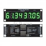
Given it seems to have two 74HC595 shift registers, having 8 outputs each, I would presume it needs to be continually driven to show a complete display, one digit being illuminated at a time.
I would guess it requires two bytes of data to be sent using SPI style clocking to indicate which digit to illuminate and another to indicate which segments of that digit to illuminate.
As to the byte order and what the bits in each byte means that can probably be figured out by experimentation if a circuit diagram can't be found.
I would send pairs of 1,1 then 2,2 - 4,4 - 8,8 - 16,16 - 32,32 - 64,64 - 128,128 and you should be able to figure out which digit and which segment those bits affect.
Then by keeping one byte fixed and cycling through the other's bits you can determine which byte controls the digits and which controls the segments.
If more than one digit or segment lights when 1,1 is sent there is some active-low logic in play but that should be easily fixable in software.
I'm not entirely sure why it has "DIO" and "RCK" - I'll need to have a read of the 74HC595 datasheet. Tie "RCK" to 0V would be my guess. And put a 1K between the PICAXE data out pin and "DIO" just to be electrically safe.
hippy
Ex-Staff (retired)
Hmm. I'm guessing the circuit of the board is something like ...I'll need to have a read of the 74HC595 datasheet.
Code:
          .------------------------------------------------------------.
          |                                                            |
         .|.        | | | | | | | |                 | | | | | | | |    |
         |_|      .-^-^-^-^-^-^-^-^-.             .-^-^-^-^-^-^-^-^-.  |
          |       | 0 1 2 3 4 5 6 7 |             | 0 1 2 3 4 5 6 7 |  |
          |       |                 |             |                 |  |
DIO <>----^------>| DIN        DOUT |------------>| DIN        DOUT |--'
       .--------->| CLK             |  .--------->| CLK             |
       |  .------>| LATCH           |  |  .------>| LATCH           |
       |  |  -.-  |                 |  |  |  -.-  |                 |
       |  |   `-->| RESET\          |  |  |   `-->| RESET\          |
       |  |   .-->| OE\             |  |  |   .-->| OE\             |
       |  |  _|_  `-----------------'  |  |  _|_  `-----------------'
       |  |                            |  |
SCK >--^--|----------------------------'  |
          |                               |
RCK >-----^-------------------------------'I am guessing the "DIO" has some sort of resistor limited feedback from the final DOUT so boards can be daisy-chained and data can be fed in from either end. With only one display board you don't have to worry about that and I expect whatever the scheme is it works and doesn't need to be worried over.
Last edited:
inglewoodpete
Senior Member
The MR pin of a 74HC595 is active low, so needs to be pulled high to run.
Last edited:
hippy
Ex-Staff (retired)
Oops, and thanks. It seems I missed that.The MR pin of a 74HC595 is active low, so needs to be pulled high to run.
This would be my first attempt at test code ...
Code:
Symbol DIO       = B.0
Symbol SCK       = B.1
Symbol RCK       = B.2

Symbol CLOCK     = SCK
Symbol LATCH     = RCK

Symbol reserveW0 = w0 ; b1:b0
Symbol digit     = b2
Symbol segments  = b3

PowerOnReset:
  Low CLOCK
  Low LATCH

MainLoop:
  Do
    ; Test digits and segments
    digit = 1
    Do
      segments = digit
      Gosub SetDigitSegments
      digit = digit * 2
    Loop Until digit = 0
    ; Test digits
    digit    = 1
    segments = 1
    Do
      Gosub SetDigitSegments
      digit = digit * 2
    Loop Until digit = 0
    ; Test segments
    digit    = 1
    segments = 1
    Do
      Gosub SetDigitSegments
      segments = segments * 2
    Loop Until segments = 0
    ; All off
    digit    = 0
    segments = 0
    Gosub SetDigitSegments
    Pause 4000
  Loop

SetDigitSegments:
  b0 = digit    : Gosub ClockOutB0_MsbFirst
  b0 = segments : Gosub ClockOutB0_MsbFirst
  High LATCH
  Low  LATCH
  Pause 1000
  Return

ClockOutB0_MsbFirst:
  For b1 = 0 To 7
    If bit7 = 0 Then
      Low  DIO
    Else
      High DIO
    End If
    High CLOCK
    Low  CLOCK
    b0 = b0 * 2
  Next
  Return
Aries
New Member
Unless it is obvious that the DIOs are linked together on the board, then the DIO (out) from one board goes to the DIO (in) on the next board to achieve the daisy-chaining. I have three 595s linked in this way in the underfloor heating controller. On the 595 itself, SRCLK is the storage register clock (used to clock pulses into the register, so you need 16 pulses to load the two registers) and then RCLK is the register clock which switches the output pins to the values just loaded. The sequence is therefore
(Set DIO , pulse SRCLK) repeat 16 times, pulse RCLK. I guess that SCK is SRCLK and RCK is RCLK.
(Set DIO , pulse SRCLK) repeat 16 times, pulse RCLK. I guess that SCK is SRCLK and RCK is RCLK.
hippy
Ex-Staff (retired)
It's a bit odd, if they aren't joined, that both ends of the board are labelled "DIO" rather than "DIN" and "DOUT" to make it clear which end data should be fed in to or taken out from. Then again I find it odd they used "SCK" and "RCK" rather than CLOCK and LATCH or something which made it more obvious what each does..Unless it is obvious that the DIOs are linked together on the board, then the DIO (out) from one board goes to the DIO (in) on the next board to achieve the daisy-chaining.
I do sometimes wonder why some manufacturers don't make it easier for their users when they must realise many are unlikely to have any product documentation. I suspect for some it's a case of getting it out there, maximising profit, by leaving others to deal with the support burden.
Aries
New Member
It wouldn't make sense to join the DIOs on one board together, because one is the input to the first digit and the other is the carry-over from the last digit. As far as SCK and RCK are concerned, the variants I used (SRCLK and RCLK) are the ones from the 74HC595 datasheet. Abbreviated to three characters they would be Register clock and Storage clock (not standard, perhaps, but not incomprehensible).
Jack Burns
New Member
I found a document which states “When sending data to the board, we send 16 bits of data. The first 8 bits are for the segments, the second 8 bits relate to the display number.”
“Note that when sending data to the 74HC595 shift- register, 0 = on, 1 = off.”
Display order
43218765
Further information:
https://www.mr.langford.co/codeclub/worksheets/rpi4_05b_74hc595.pdf
“Note that when sending data to the 74HC595 shift- register, 0 = on, 1 = off.”
Display order
43218765
Further information:
https://www.mr.langford.co/codeclub/worksheets/rpi4_05b_74hc595.pdf
1968neil
Senior Member
I received the module this morning and i can confirm that ALL of the pins are duplicated at either end and i can measure continuity between each header pin to the corresponding pin.
It would seem that this this is designed as a stand alone module and not designed for adding more modules in series.
I tried your code @hippy and it does give me some sort of display but it is jumbled, is it easy to convert as per Jacks suggestion ?
I'm a bit green when it comes to this particular area ........ (analogue audio and RF is my field)
hippy
Ex-Staff (retired)
Thanks to Jacks excellent sleuthing it should be possible. Untested but I think this should convert digit order so digit 1 is on the left, 8 is on the right, and only one segment is lit at a time ...I tried your code @hippy and it does give me some sort of display but it is jumbled, is it easy to convert as per Jacks suggestion ?
Code:
SetDigitSegments:
  ; Convert 'digit' bit setting to digit number
  LookDown digit, (0, 1, 2, 4, 8, 16, 32, 64, 128), b1
  ; Our b1 digit value  : 0   1   2   3   4   5   6   7   8
  ; Display digit order :     4   3   2   1   8   7   6   5
  ; Display select bits : 0   8   4   2   1 128  64  32  16
  LookUp b1, (0, 8, 4, 2, 1, 128, 64, 32, 16), b1
  b0 = b1             : Gosub ClockOutB0_MsbFirst
  b0 = segments ^ $FF : Gosub ClockOutB0_MsbFirst
  High LATCH
  Low  LATCH
  Pause 1000
Return1968neil
Senior Member
I have attached a video clip link to show you what i am getting as im struggling to make sense of the result.......
Any ideas ?
Thanks")
Video Clip
Any ideas ?
Thanks
Video Clip
Hi,
The LEDs are wired "Active Low" (i.e. Logic 0 = On , Logic 1 = Off) so you need to look at the sequence of the segments or characters which are OFF.
A "quick fix" to the code might be to change the two "b0" lines as follows:
Note that the ^ symbol represents XOR (Exclusive OR) which applied to $FF (=%11111111 or 255) inverts all the bits, as I believe will b0 = NOT b1 , etc.
Cheers, Alan.
The LEDs are wired "Active Low" (i.e. Logic 0 = On , Logic 1 = Off) so you need to look at the sequence of the segments or characters which are OFF.
A "quick fix" to the code might be to change the two "b0" lines as follows:
Code:
  b0 = b1 ^ $FF           : Gosub ClockOutB0_MsbFirst
b0 = segments : Gosub ClockOutB0_MsbFirstCheers, Alan.

hippy
Ex-Staff (retired)
Thanks for that video - At least it's workingI have attached a video clip link to show you what i am getting as im struggling to make sense of the result.......
Beyond that it seems we have about every mistake we possibly could have, that we now have digit and segments inverted, digit and segment data sent in the wrong order, digit ordering not mapping to physical digit, and the segment bit numbering doesn't seem ideal either,
And, hands up, that what Jack posted does say segments first.
Allycat has probably nailed the inversion, that it's needed for digits but not for segments. I would try this which might move the digits from right to left -
Code:
SetDigitSegments:
  b0 = segments       : Gosub ClockOutB0_MsbFirst
  b0 = digit    ^ $FF : Gosub ClockOutB0_MsbFirst
  High LATCH
  Low  LATCH
  Pause 1000
  Return
Code:
SetDigitSegments:
  b0 = segments  : Gosub ClockOutB0_MsbFirst
  ; Convert 'digit' bit setting to digit number
  LookDown digit, (0, 1, 2, 4, 8, 16, 32, 64, 128), b1
  ; Our b1 digit value  : 0   1   2   3   4   5   6   7   8
  ; Display digit order :     4   3   2   1   8   7   6   5
  ; Display select bits : 0   8   4   2   1 128  64  32  16
  LookUp b1, (0, 8, 4, 2, 1, 128, 64, 32, 16), b1
  b0 = b1 ^ $FF : Gosub ClockOutB0_MsbFirst
  High LATCH
  Low  LATCH
  Pause 1000
ReturnHi,
Eventually, the Data Tables from "Mr Langford's" code might be useful. It's more common to number the digits and segments from 0 to 7 and Right to Left, (i.e. LS Bit first), but Left-shifting can be a little more convenient with PICaxe.
The dp/segments can be identified by starting with the digits having only one segment/bit not lit (= logic 1), i.e. 8 , then 0 , 6 , 9 , A (or _ and - lit) and then comparing 1 to 7 , 5 to 9 and 2 to 3. Note that some of the alphabetic characters shown above are not unique, e.g. S / 5 , 2 / Z , others can be in lower case such as: b , d , (e) , q , r , t , y , and a few not very intuitive such as X , K , M , V , W. Alternatively, some characters can be tilted "sideways", e.g. m = E , w = 3 and "10".
Cheers, Alan.
Eventually, the Data Tables from "Mr Langford's" code might be useful. It's more common to number the digits and segments from 0 to 7 and Right to Left, (i.e. LS Bit first), but Left-shifting can be a little more convenient with PICaxe.
Code:
  [0,0,0,0,1,0,0,0], # Position 0 / 8th display
  [0,0,0,0,0,1,0,0], # Position 1 / 7th display
  [0,0,0,0,0,0,1,0], # Position 2 / 6th display
  [0,0,0,0,0,0,0,1], # Position 3 / 5th display
  [1,0,0,0,0,0,0,0], # Position 4 / 4th display
  [0,1,0,0,0,0,0,0], # Position 5 / 3rd display
  [0,0,1,0,0,0,0,0], # Position 6 / 2nd display
  [0,0,0,1,0,0,0,0]  # Position 7 / 1st display

;  bits 7 6 5 4 3 2 1 0
  "0": [1,1,0,0,0,0,0,0],  segments:
  "1": [1,1,1,1,1,0,0,1],        --0--
  "2": [1,0,1,0,0,1,0,0],       5     1
  "3": [1,0,1,1,0,0,0,0],        --6--
  "4": [1,0,0,1,1,0,0,1],       4     2
  "5": [1,0,0,1,0,0,1,0],        --3--
  "6": [1,0,0,0,0,0,1,0],               7 (dp)
  "7": [1,1,1,1,1,0,0,0],
  "8": [1,0,0,0,0,0,0,0],
  "9": [1,0,0,1,0,0,0,0],
  "A": [1,0,0,0,1,0,0,0],
  "B": [1,0,0,0,0,0,1,1],
  "C": [1,1,0,0,0,1,1,0],
  "D": [1,0,1,0,0,0,0,1],
  "E": [1,0,0,0,0,1,1,0],
  "F": [1,0,0,0,1,1,1,0],
  "G": [1,1,0,0,0,0,1,0],
  "H": [1,0,0,0,1,0,0,1],
  "I": [1,1,0,0,1,1,1,1],
  "J": [1,1,1,1,0,0,0,1],
  "K": [1,0,0,0,1,0,1,0],
  "L": [1,1,0,0,0,1,1,1],
  "M": [1,1,0,1,0,1,0,0],
  "N": [1,1,0,0,1,0,0,0],
  "O": [1,1,0,0,0,0,0,0],
  "P": [1,0,0,0,1,1,0,0],
  "Q": [1,0,0,1,1,0,0,0],
  "R": [1,1,0,0,1,1,1,0],
  "S": [1,0,0,1,0,0,1,0],
  "T": [1,0,0,0,0,1,1,1],
  "U": [1,1,0,0,0,0,0,1],
  "V": [1,1,0,1,0,0,0,1],
  "W": [1,1,1,0,0,0,1,0],
  "X": [1,0,1,1,0,1,1,0],
  "Y": [1,0,0,1,0,0,0,1],
  "Z": [1,0,1,0,0,1,0,0],
  " ": [1,1,1,1,1,1,1,1],
  "-": [1,0,1,1,1,1,1,1],
"_": [1,1,1,1,0,1,1,1]Cheers, Alan.
To my mind, the board described would seem to need constant refreshing in order to display multiple digits at once. Assuming this to be the case, it would surely defeat the point of having the 74HC595s at all, other than to reduce the pins needed to connect to the display(s). In order to have eight 7 segment displays lit up won't the PicAxe be running flat out trying to maintain a flicker free display?
I've designed many displays using 74HC595s, the advantage of using one 595 per seven segment display is that once the display(s) is(are) set, the processor can go away and do other 'stuff' with the display(s) staying lit, the processor only needing to update the display when the information being shown needs to be altered. Sending eight bytes in one 'blast' may take a moment or so, but this display would seem to need sixteen bytes to be sent, in quick rotaion.
I've designed many displays using 74HC595s, the advantage of using one 595 per seven segment display is that once the display(s) is(are) set, the processor can go away and do other 'stuff' with the display(s) staying lit, the processor only needing to update the display when the information being shown needs to be altered. Sending eight bytes in one 'blast' may take a moment or so, but this display would seem to need sixteen bytes to be sent, in quick rotaion.
1968neil
Senior Member
Good Morning Chaps,
I uploaded another video, this is with the code change that Hippy suggested
Video 2
Any ideas ? I am beginning to think this module is a real oddball, its quite frustrating as i can seem to find no datasheet for it, yet lots of them for sale on the usual platforms !!
Thanks for all the input, it would be nice to get to the bottom of it, but completely understand if you would rather forget it !!
I uploaded another video, this is with the code change that Hippy suggested
Video 2
Code:
SetDigitSegments:
  b0 = segments  : Gosub ClockOutB0_MsbFirst
  ; Convert 'digit' bit setting to digit number
  LookDown digit, (0, 1, 2, 4, 8, 16, 32, 64, 128), b1
  ; Our b1 digit value  : 0   1   2   3   4   5   6   7   8
  ; Display digit order :     4   3   2   1   8   7   6   5
  ; Display select bits : 0   8   4   2   1 128  64  32  16
  LookUp b1, (0, 8, 4, 2, 1, 128, 64, 32, 16), b1
  b0 = b1 ^ $FF : Gosub ClockOutB0_MsbFirst
  High LATCH
  Low  LATCH
  Pause 1000
ReturnThanks for all the input, it would be nice to get to the bottom of it, but completely understand if you would rather forget it !!
Hi,
The OP hasn't posted a link to his particular display, indicating how "low cost" it might be, however nearly all that I found look very similar but use the MAX7219 chip, which does include all the necessary display multiplexing and drivers, from around £4 for UK stock. I've never used that chip, but code to drive it from a PICaxe looks to be a more interesting and worthwhile project/challenge.
Cheers, Alan.
Yes, I think we've been mislead by the "Demo Program" because it's showing the same digit on all the displays (except one which is "disabled"). A real "live" display will need to be updated continuously about every 2-3 milliseconds (usually by a timer interrupt). I don't believe that's even possible with a PICaxe, except by using its on-chip SPI Hardware, a feature that I would like to investigate sometime (using an M2 with POKESFR commands, not an X2 chip), but probably not now......., other than to reduce the pins needed to connect to the display(s). In order to have eight 7 segment displays lit up won't the PicAxe be running flat out trying to maintain a flicker free display?
The OP hasn't posted a link to his particular display, indicating how "low cost" it might be, however nearly all that I found look very similar but use the MAX7219 chip, which does include all the necessary display multiplexing and drivers, from around £4 for UK stock. I've never used that chip, but code to drive it from a PICaxe looks to be a more interesting and worthwhile project/challenge.
Cheers, Alan.
hippy
Ex-Staff (retired)
Thanks; it's so much easier when one can see what's happening. I think we are just one step away from having it working ...Any ideas ? I am beginning to think this module is a real oddball
Rich (BB code):
SetDigitSegments:
  b0 = segments ^ $FF : Gosub ClockOutB0_MsbFirst
  ; Convert 'digit' bit setting to digit number
  LookDown digit, (0, 1, 2, 4, 8, 16, 32, 64, 128), b1
  ; Our b1 digit value  : 0   1   2   3   4   5   6   7   8
  ; Display digit order :     4   3   2   1   8   7   6   5
  ; Display select bits : 0   8   4   2   1 128  64  32  16
  LookUp b1, (0, 8, 4, 2, 1, 128, 64, 32, 16), b1
  b0 = b1 : Gosub ClockOutB0_MsbFirst
  High LATCH
  Low  LATCH
  Pause 1000
  Return
Code:
LookDown digit, (0, 128, 64, 32, 16, 8, 4, 2, 1), b1hippy
Ex-Staff (retired)
That is my presumption. It may be possible because I did manage to bit-bang an 8-digit 7-segment display a segment at a time and get that flicker-free but that did require highly optimised code and there wasn't much time for anything else.To my mind, the board described would seem to need constant refreshing in order to display multiple digits at once ... In order to have eight 7 segment displays lit up won't the PicAxe be running flat out trying to maintain a flicker free display?
This is digit at a time multiplexing so faster, but having to send 16-bits per digit will likely make it slower. By moving to hardware SPI things can probably be made fast enough to be flicker free.
Something like a MAX7219 which can take data whenever it changes and do the display refreshing itself would be much more appropriate for PICAXE use.
This would be my effort to get a static display where each digit is different. In theory it should show "1234.5678" but I might have messed the digit order up again or introduced different bugs -
Code:
Symbol DIO       = B.0
Symbol SCK       = B.1
Symbol RCK       = B.2

Symbol CLOCK     = SCK
Symbol LATCH     = RCK

;                         .GFEDCBA
Symbol BLANK     = $FF ^ %00000000   ;  AAA
Symbol ONE       = $FF ^ %00000110   ; F   B
Symbol TWO       = $FF ^ %01011011   ; F   B
Symbol THREE     = $FF ^ %01001111   ;  GGG
Symbol FOUR      = $FF ^ %01100110   ; E   C
Symbol FIVE      = $FF ^ %01101101   ; E   C
Symbol SIX       = $FF ^ %01111101   ;  DDD  o
Symbol SEVEN     = $FF ^ %00000111
Symbol EIGHT     = $FF ^ %01111111
Symbol NINE      = $FF ^ %01101111
Symbol DP        = $FF ^ %10000000

Symbol reserveW0 = w0 ; b1:b0
Symbol digitBit  = b2

Symbol digit4    = b10
Symbol digit3    = b11
Symbol digit2    = b12
Symbol digit1    = b13
Symbol digit8    = b14
Symbol digit7    = b15
Symbol digit6    = b16
Symbol digit5    = b17

PowerOnReset:
  SetFreq M32
  Low CLOCK
  Low LATCH

MainLoop:
  digit1 = ONE        ; Display 1234.5678
  digit2 = TWO
  digit3 = THREE
  digit4 = FOUR & DP
  digit5 = FIVE
  digit6 = SIX
  digit7 = SEVEN
  digit8 = EIGHT
  Do
    Gosub UpdateDisplay
  Loop

UpdateDisplay:
  digitBit = 1
  bPtr = 10
  Do
    b0 = @bPtrInc : Gosub ClockOutB0_MsbFirst
    b0 = digitBit : Gosub ClockOutB0_MsbFirst
    High LATCH
    Low  LATCH
    digitBit = digitBit + digitBit
  Loop Until digitBit = 0
  Return

ClockOutB0_MsbFirst:
  For b1 = 0 To 7
    If bit7 = 0 Then
      Low  DIO
    Else
      High DIO
    End If
    High CLOCK
    Low  CLOCK
    b0 = b0 * 2
  Next
  Return
Last edited:
hippy
Ex-Staff (retired)
Actually it's a bit more involved than that. In order to make persistence of vision work, the entire display must be updated at a 50 Hz or better rate and, digit at a time means, selecting a new digit for display every 2ms or so as AllyCat notes.By moving to hardware SPI things can probably be made fast enough to be flicker free.
The speed of getting data out isn't necessarily critical where latching is involved as here; that can take up to 2ms during which time the last digit will be being displayed which is fine.
I am assuming that the latching here is fast enough that it doesn't require the last digit to be turned off before the next is turned on. If there is ghosting that will require additional data to be sent, though only 8 bits as one only needs to clear all segments, won't have to care what may have been shifted into the digits register.
The bottom line is that the display has to be continually refreshed at a fast rate or it flickers. I expect it will mean this type of display will only be useful in clock and similar projects where the majority of time can be spent on updating the display, where updating the data to display can be done very quickly.
hippy
Ex-Staff (retired)
No that's exactly how it should beThe plot thickens .........
First a single digit and segment are selected at a time. That's working; the digit illuminated moves from 1 on the right to 8 on the left, and at the same time the segment cycles clockwise from top to finally end on the decimal point.
Second the digits are stepped from 1 on the right to 8 on the left, while only segment bit 0 (top) is lit.
Third only digit 1 is selected and the segments are cycled from bit 0 (top) to bit 7 (decimal point).
Finally the display is blanked for five seconds before the above repeats again. Success !
D'Oh! ...The code in post 21 gives a completely blank display....
Code:
UpdateDisplay:
  digitBit = 0
Rich (BB code):
UpdateDisplay:
digitBit = 11968neil
Senior Member
@hippy , I now have the digits working , They are flickering as per the video, at least we now have the correct format.
Is it simple to get the updates to just be a simple number step thru a digit at a time ?
The reason for learning the 74HC595 was to test banks of eight of them each driving a single seven segment display.
A basic test set up for both the IC and the display etc.
These would be cascaded via the DIO ports etc.
I am assuming this is possible ?
I am so impressed that you stuck with this as i was pulling my hair out as i should be so simple (famous last words)
Video 4
, They are flickering as per the video, at least we now have the correct format.Is it simple to get the updates to just be a simple number step thru a digit at a time ?
The reason for learning the 74HC595 was to test banks of eight of them each driving a single seven segment display.
A basic test set up for both the IC and the display etc.
These would be cascaded via the DIO ports etc.
I am assuming this is possible ?
I am so impressed that you stuck with this as i was pulling my hair out as i should be so simple (famous last words)
Video 4
hippy
Ex-Staff (retired)
Not quite sure how you mean but this should show an incrementing number on the display -They are flickering as per the video, at least we now have the correct format.
Is it simple to get the updates to just be a simple number step thru a digit at a time ?
Code:
Symbol DIO       = B.0
Symbol SCK       = B.1
Symbol RCK       = B.2

Symbol CLOCK     = SCK
Symbol LATCH     = RCK

;                         .GFEDCBA
Symbol BLANK     = $FF ^ %00000000   ;  AAA
Symbol ZERO      = $FF ^ %00111111   ; F   B
Symbol ONE       = $FF ^ %00000110   ; F   B
Symbol TWO       = $FF ^ %01011011   ;  GGG
Symbol THREE     = $FF ^ %01001111   ; E   C
Symbol FOUR      = $FF ^ %01100110   ; E   C
Symbol FIVE      = $FF ^ %01101101   ;  DDD  o
Symbol SIX       = $FF ^ %01111101
Symbol SEVEN     = $FF ^ %00000111
Symbol EIGHT     = $FF ^ %01111111
Symbol NINE      = $FF ^ %01101111
Symbol DP        = $FF ^ %10000000

Symbol reserveW0 = w0 ; b1:b0
Symbol counter   = w1 ; b3:b2
Symbol digitBit  = b2

Symbol digit4    = b10
Symbol digit3    = b11
Symbol digit2    = b12
Symbol digit1    = b13
Symbol digit8    = b14
Symbol digit7    = b15
Symbol digit6    = b16
Symbol digit5    = b17

PowerOnReset:
  SetFreq M32
  Low CLOCK
  Low LATCH

MainLoop:
  counter = 0
  Do
    Gosub SetCounterDigits
    Gosub UpdateDisplay
    counter = counter + 1
  Loop

SetCounterDigits:
  ; Split the 16-bit counter into numeric digit values 0-9
  digit5  = counter / 10000
  digit4  = counter / 1000  % 10
  digit3  = counter / 100   % 10
  digit2  = counter / 10    % 10
  digit1  = counter         % 10
  ; Blank leading zeroes, blank digit value = 10
  If digit5 = 0 Then
     digit5 = 10
     If digit4 = 0 Then
        digit4 = 10
        If digit3 = 0 Then
           digit3 = 10
           If digit2 = 0 Then
              digit2 = 10
           End If
        End If
     End If
  End If
  ; Convert numeric digit values into display segments
  LookUp digit5, (ZERO, ONE, TWO, THREE, FOUR, FIVE, SIX, SEVEN, EIGHT, NINE, BLANK), digit5
  LookUp digit4, (ZERO, ONE, TWO, THREE, FOUR, FIVE, SIX, SEVEN, EIGHT, NINE, BLANK), digit4
  LookUp digit3, (ZERO, ONE, TWO, THREE, FOUR, FIVE, SIX, SEVEN, EIGHT, NINE, BLANK), digit3
  LookUp digit2, (ZERO, ONE, TWO, THREE, FOUR, FIVE, SIX, SEVEN, EIGHT, NINE, BLANK), digit2
  LookUp digit1, (ZERO, ONE, TWO, THREE, FOUR, FIVE, SIX, SEVEN, EIGHT, NINE       ), digit1
  Return

UpdateDisplay:
  digitBit = 0
  bPtr = 10
  Do
    b0 = @bPtrInc : Gosub ClockOutB0_MsbFirst
    b0 = digitBit : Gosub ClockOutB0_MsbFirst
    High LATCH
    Low  LATCH
    digitBit = digitBit + digitBit
  Loop Until digitBit = 0
  Return

ClockOutB0_MsbFirst:
  For b1 = 0 To 7
    If bit7 = 0 Then
      Low  DIO
    Else
      High DIO
    End If
    High CLOCK
    Low  CLOCK
    b0 = b0 * 2
  Next
ReturnHaving one 74HC595 per display should be easy enough, simpler than what we are doing here, and that appears to be how tmfkan has done it. Send eight bytes of digit data, setting the segments for each digit, activate LATCH, and the display will be set and stay flicker-free until the next data is written.The reason for learning the 74HC595 was to test banks of eight of them each driving a single seven segment display.
hippy
Ex-Staff (retired)
I guess I misunderstood how you were intending to use the display board. If you just want to use a single digit sou can test setting segments on that it can be as simple as -Update, i now have it without the flickering by slowing the setfreq down to setfreqM1 and its now working in a way that i can cope with without having a fit
Code:
Symbol DIO       = B.0
Symbol SCK       = B.1
Symbol RCK       = B.2

Symbol CLOCK     = SCK
Symbol LATCH     = RCK

;                   .GFEDCBA
Symbol BLANK     = %00000000   ;  AAA
Symbol ZERO      = %00111111   ; F   B
Symbol ONE       = %00000110   ; F   B
Symbol TWO       = %01011011   ;  GGG
Symbol THREE     = %01001111   ; E   C
Symbol FOUR      = %01100110   ; E   C
Symbol FIVE      = %01101101   ;  DDD  o
Symbol SIX       = %01111101
Symbol SEVEN     = %00000111
Symbol EIGHT     = %01111111
Symbol NINE      = %01101111
Symbol DP        = %10000000

Symbol reserveW0 = w0 ; b1:b0

PowerOnReset:
  Low CLOCK
  Low LATCH

MainLoop:
  Do
    b0 = FOUR       ; Change this to the segments you want to set
    Gosub SetDigit
  Loop

SetDigit:
  b0 = b0 ^ $FF : Gosub ClockOutB0_MsbFirst
  b0 = 1        : Gosub ClockOutB0_MsbFirst
  High LATCH
  Low  LATCH
  Return

ClockOutB0_MsbFirst:
  For b1 = 0 To 7
    If bit7 = 0 Then
      Low  DIO
    Else
      High DIO
    End If
    High CLOCK
    Low  CLOCK
    b0 = b0 * 2
  Next
ReturnHairy Animal
Member
Some time ago, Hippy and others were very helpful in writing some very elegant code for the very cheap but similar MAX7219 displays I was trying to use, see "Pixel scrolling of a text message on 8x8 LED matrix displays with a MAX7219". They don't need continuous refreshing and the PicAxe is fast enough to run a sophisticated scrolling text display as well as numeric.
1968neil
Senior Member
I have a small problem that i am sure is not possible to correct without changing my pcb.
I layed out a pcb using common cathode 7 segment displays that i had previously tested with the 74HC595 with help from the forum.
A few weeks later, it now turns out the 74HC595 i was meant to interface with are actually TPIC6B595 which look like they only switch low ? (Common Anode)
This is very frustrating but none the less a problem i need to rectify.
Is it possible to make the TPIC6B595 drive the common cathode displays or am i simply better off just starting a new layout with common Anode ?
https://www.ti.com/lit/ds/symlink/tpic6b595.pdf
Hi,
I don't believe that you have ever posted a circuit diagram, but yes, the TPIC6B595 appears to have only a pull-down capability. However, AFAIK that (high current) is what is required for a Common Cathode display, because the Cathode Driver needs to sink the current from up to 8 Anodes. So, as far as I can see, you would still need a "normal" HC595 device (or similar) to drive (current into) the Anodes (although that current will still be far lower than 1/8 of the maximum sink capability of the TPIC6B595).
Basically it's just an 8x8 multiplexed array, so you could drive Common Anodes or Common Cathodes , but the software will be more "untidy" if you try to drive one segment of each digit in parallel, during each display period of the cycle.
Cheers Alan.
hippy
Ex-Staff (retired)
If you are driving each 7-segment Common Cathode display with its own 595 register it might be possible to modify your PCB to make it work.Is it possible to make the TPIC6B595 drive the common cathode displays or am i simply better off just starting a new layout with common Anode ?
A traditional 'set high or set low' 595 circuit for Common Cathode would usually be as below -
Code:
.----.    __    ............
|    |---|__|---:--|>|--.  :
|    |---|__|---:--|>|--{  :
:    :    __    :       :  :
|    |---|__|---:--|>|--{  :
|    |---|__|---:--|>|--^--:---.
`----' :..........: _|_ 0VFor an 'open-circuit or pull-low' power 595 that won't work, because there is no way for the 595 to source current into the segments.
However you could achieve that by always having current flow into each segment, use the 595 to pull the segment anode low so no current flows through the segment itself -
Code:
       --.-.---.-.-- 5V
        .|.|. .|.|.
        |_|_| |_|_|
.----.   | |   | |   ............
|    |---^-|---|-|---:--|>|--.  :
|    |-----^---|-|---:--|>|--{  :
:    :         | |   :       :  :
|    |---------^-|---:--|>|--{  :
|    |-----------^---:--|>|--^--:---.
`----' :..........: _|_ 0VThe downside of such a modification is that each segment resistor will always be drawing current, whether lighting a segment or pulling it low to prevent lighting. Typical current will be more than when current is only drawn when a segment is lit. It may also be that, if the outputs don't pull hard enough to 0V, there may be residual current which flows through segments which causes them to light slightly even when off.
It might be worth trying but I would suggest redesigning the PCB and using Common Anode displays is the proper course of action. Simply using traditional 595 instead of what you have is likely easier and cheaper.
1968neil
Senior Member
I am building a test jig for a module that i use at work as the manufacturer wont support the product anymore.
The issue is we have 1000's of modules with our current systems and we get a lot of them to repair from other clients.
The basic set up is :
The 8x TPIC6B595 on this board are driven by my PICAXE and the outputs in turn feed an IDC64 way header.
The header is then connected to my PCB which has x8 7 Segment displays.
So each TPIC has its own display and they are all driven by on the same CLOCK/DATA lines and each Serial in is fed from the serial out of the previous TPIC.
The TPIC IC's on the PCB are prone to failure and this test jig is meant to give me a quick indication of which device is faulty, they are all SMD so its not a quick swap out if you suspect one to be faulty etc.
I use PICAXE for a lot of this sort of fixture design as they are wonderful little devices and so quick to prototype.
I think i will most likely just re-track and order a new pcb from JLCPCB as they are so inexpensive nowadays.
I'm happy to share the schematic if anyone is interested enough ?
Once again, thanks guys you really are top drawer
hippy
Ex-Staff (retired)
That makes sense. If I have read that right you have a board similar to below which you need to test -The TPIC IC's on the PCB are prone to failure and this test jig is meant to give me a quick indication of which device is faulty, they are all SMD so its not a quick swap out if you suspect one to be faulty etc.
Code:
             _____________________ _ _ _________
      ......|_____________________ _ _ _________|...
      :       ||||         ||||            ||||    :
      :     .-^^^^-.     .-^^^^-.        .-^^^^-.  :
DAT --:---->|      |---->|      |- - - ->|      |  :
      :  .->|      |  .->|      |     .->|      |  :
      :  |  `------'  |  `------'     |  `------'  :
CLK --:--^------------^----------- - -'            :
:............................................:It seems to me that if you simply pull each of the 64 outputs up to 5V using resistors that could then work with Common Cathode displays as described, assuming those Common Cathodes all connected to 0V. That should also work if you have all the Common Cathodes on your display board going to a power 595.
I think you need to describe exactly what you currently have on your display board, a schematic would certainly be useful to see.
hippy
Ex-Staff (retired)
Thinking about the fault conditions you are trying to identify - Rather than using 7-segment displays, it might be easier to use eight DIL LED arrays, stacked one above the other, or even an 8 x 8 LED display, even discrete LED's.
It would seem to me that would make it easier to see which chips or individual outputs had failed by making the display scan vertically and horizontal.
It would seem to me that would make it easier to see which chips or individual outputs had failed by making the display scan vertically and horizontal.
1968neil
Senior Member
Hi Hippy,
Thanks for your words of wisdom, hindsight is a wonderful thing
I have attached a schematic of my set up, i have amended the project now to use Common anode and will probably re-order a pcb to test.
I would add the pullups but the whole board is SMD so not quite that easy.
I may do what you have suggested and maybe use a dil array, that would certainly be an option.
The schematic attached is the original design and has NOT been updated for common anode.
Thanks again for the assistance and the wisdom 
Thanks for your words of wisdom, hindsight is a wonderful thing
I have attached a schematic of my set up, i have amended the project now to use Common anode and will probably re-order a pcb to test.
I would add the pullups but the whole board is SMD so not quite that easy.
I may do what you have suggested and maybe use a dil array, that would certainly be an option.
The schematic attached is the original design and has NOT been updated for common anode.
Thanks again for the assistance and the wisdom
Attachments
-
146.3 KB Views: 10