I am not getting the results I expected from a 74LS165. I have tried two different devices both 74LS165.
My code is:
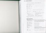
'Recieve a byte from a 74xx165
'OPTIONS PICAXE-08
#PICAXE-08m
symbol latchin = 4
symbol datain = pin3
symbol clk = 2
symbol inbyte = b1
symbol bcounter = b2
pause 1000
sertxd ( "OK" , 13,10)
init:
high latchin 'init latch to hi state
main:

gosub bytein
sertxd ( #inbyte , 13,10)

goto main
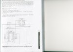
bytein:
pulsout latchin,1 'latch the input into -inbyte-
inbyte = 0 'init val to 0
for bcounter = 1 to 8 'count to 8
inbyte = inbyte / 2 'shift right
if datain = 0 then 'test for data
goto nobit 'test for a data bit
end if
inbyte = inbyte | $80 ' set bit 7 of byte var
nobit: pulsout clk,1 ' clock the shift register
next bcounter
return
I do not think there is an error in the code. Yes/No?
Is this an issue with using an LS device? Should I have used an HC device?
And, if the LS is the issue - can I work around the issue by pulling all the 74LS65 input port higher?
Or, I am looking in the wrong place again?
Anobium
My code is:
'Recieve a byte from a 74xx165
'OPTIONS PICAXE-08
#PICAXE-08m
symbol latchin = 4
symbol datain = pin3
symbol clk = 2
symbol inbyte = b1
symbol bcounter = b2
pause 1000
sertxd ( "OK" , 13,10)
init:
high latchin 'init latch to hi state
main:
gosub bytein
sertxd ( #inbyte , 13,10)
goto main
bytein:
pulsout latchin,1 'latch the input into -inbyte-
inbyte = 0 'init val to 0
for bcounter = 1 to 8 'count to 8
inbyte = inbyte / 2 'shift right
if datain = 0 then 'test for data
goto nobit 'test for a data bit
end if
inbyte = inbyte | $80 ' set bit 7 of byte var
nobit: pulsout clk,1 ' clock the shift register
next bcounter
return
I do not think there is an error in the code. Yes/No?
Is this an issue with using an LS device? Should I have used an HC device?
And, if the LS is the issue - can I work around the issue by pulling all the 74LS65 input port higher?
Or, I am looking in the wrong place again?
Anobium
Last edited:
")