The project was the sensor for a timing gate for a race.
The requirements were 1, fast response, 2, no wires across the track, 3, easy setup, i.e, no accurate alignment requirements, 4, must work outdoors.
Most off-the-shelf sensors, as used by the millions in the industrial world, have response times measured in 10's of mS. I needed millisecond response. An off-the-shelf industrial sensor with millisecond response would cost more than the whole budget for the project, by a factor of 10 !.
No wires across the track meant either seperate PSUs, or retro-reflectors, which also met requirement 3, no alignment needed.
Lots of Googling ( maybe it was Alta Vista, or Jeeves, it was back in the day ! ) and I found the S6986. It looked very attractive. It was originally designed for tasks like paper detection in printers, where it needed to detect anything from thin white paper to thick black postcard.
The technique it uses is to frequency drive the source, usually an IR LED, and simultaneously monitor the ( built in ) photosensor. Because the TX and RX are sychronised they can be correlated. Using these features, the S6986 it is able to detect weak reflections from black card, even when exposed to high ambient light. Requirement 4 - sorted !
Because the photo-diode in the S6986 is an IR device I was unsure how it would respond to a Red laser, or even if it could drive a laser.
So I bought a couple and started experimenting. ( Or should I call it evaluating. That sounds much more professional
")
)
I found it could drive lasers easily, but the cheap 'pointer' lasers worked best. These have only a simple resistor to limit the current, but the more expensive lasers have a control IC which can't switch quickly enough.
Regarding the frequency mis-match between IR and Red light, I expect the S6986 it not working at its optimum, but its good enough for what I needed.
Retro-reflectors are on every car !.
The red reflectors are moulded with dozens of 'corner' mirrors. Three mirrors arranged as a 3D corner will reflect a light beam back to the source, usually the headlight of the car behind.
The number plate material is different in that the corner reflectors are tiny glass beads. A glass sphere on a reflective surface will do the same as corner mirrors. Similar material is available in sheets and rolls from the usual sources, and comes in a wide range of styles and colours, even black !
I tried the industrial versions of the corner reflectors, but found the laser beam just fragmented into a million sparkles. I think (a) they are optimised for IR, and (b) they are not designed for very narrow, high intensity beams like lasers.
However, the glass bead ( or probably plastic bead ) material worked perfectly, and that's what I used. A sheet 4in wide meant the alignment was not critical.
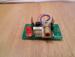
The finished sensor is pictured in post #12. This has the S6986 and the cheap laser, along with a 'normal' LED driven by a transistor to show when a signal is received.
Is that enough elucidation ?
Cheers,
Buzby