StigOfTheDump
Senior Member
Hi
I got some 4x4 keypads today. I found some code by Hippy but it is a bit too complicated for me to understand. The symbol definitions had ORs in them and some of the statements were ANDing masks and pins then XORing them with something else. Just too much for my head at this stage.
I wrote some code that seems to work and would appreciate it, if someone could cast their eye over it. The existing gosubs were just so that I can see that it is doing the right thing. The eventual intention is for this to be a gosub that I can call. Many of my projects will need a similar keypad input and I don't want it to fall to bits because of some scenario that I've overlooked.
Without the subroutines it comes in at about 100 bytes which seems a lot for reading 16 buttons. Also if the button values had to be displayed it would need a look-up table.
I didn't use any dirBs. Did I need to or are they implied by my commands?
The select case bit seems rather clumsy but I couldn't find a way to do it with loops and bits.
I've used up 4 variables, even with recycling one of them. The b1=b0-4*4+b2 line doesn't work as b1=b0-4*4+b1. I think that must be the left to right maths changing the b1 before it has been read. I could have saved a variable there.
Has any body any thoughts/tips/gaping great holes spotted?
I got some 4x4 keypads today. I found some code by Hippy but it is a bit too complicated for me to understand. The symbol definitions had ORs in them and some of the statements were ANDing masks and pins then XORing them with something else. Just too much for my head at this stage.
I wrote some code that seems to work and would appreciate it, if someone could cast their eye over it. The existing gosubs were just so that I can see that it is doing the right thing. The eventual intention is for this to be a gosub that I can call. Many of my projects will need a similar keypad input and I don't want it to fall to bits because of some scenario that I've overlooked.
Without the subroutines it comes in at about 100 bytes which seems a lot for reading 16 buttons. Also if the button values had to be displayed it would need a look-up table.
I didn't use any dirBs. Did I need to or are they implied by my commands?
The select case bit seems rather clumsy but I couldn't find a way to do it with loops and bits.
I've used up 4 variables, even with recycling one of them. The b1=b0-4*4+b2 line doesn't work as b1=b0-4*4+b1. I think that must be the left to right maths changing the b1 before it has been read. I could have saved a variable there.
Code:
#Picaxe 18M2
#Terminal 4800
'16 key 4x4 matrix keypad
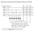
'INPUTS
'B.0 1 2 3 A
'B.1 4 5 6 B
'B.2 7 8 9 C
'B.3 * 0 # D
'OUTPUTS B.4 B.5 B.6 B.7
main:
for b0=B.4 to B.7 'Output to one column at a time
high b0 'Switch on that output
b3=pinsB & %00001111 'See which row is pressed
do
b1=pinsB & %00001111 'Wait until button is released
loop while b1<>0
select case b3
case 1 :b2=1 'If only row 1
case 2 :b2=2 'If only row 2
case 4 :b2=3 'If only row 3
case 8 :b2=4 'If only row 4
else b2=0 'Discount any other combinations
endselect
low b0 'Switch off the output
b1=b0-4*4+b2 'Add 4x column to row (to get unique 1-16 value) '
if b2=0 then let b1=0 endif 'Wrong combination = no results
'Select subroutine to visit
on b1 gosub btn0,btn1,btn2,btn3,btn4,btn5,btn6,btn7,btn8,btn9,btn10,btn11,btn12,btn13,btn14,btn15,btn16
next b0 'Next column
goto main
btn0: 'Empty routine for wrong combination
return
btn1: 'Show which button was pressed
sertxd ("Button 1 pressed",cr,lf)
return
btn2:
sertxd ("Button 4 pressed",cr,lf)
return
btn3:
sertxd ("Button 7 pressed",cr,lf)
return
btn4:
sertxd ("Button * pressed",cr,lf)
return
btn5:
sertxd ("Button 2 pressed",cr,lf)
return
btn6:
sertxd ("Button 5 pressed",cr,lf)
return
btn7:
sertxd ("Button 8 pressed",cr,lf)
return
btn8:
sertxd ("Button 0 pressed",cr,lf)
return
btn9:
sertxd ("Button 3 pressed",cr,lf)
return
btn10:
sertxd ("Button 6 pressed",cr,lf)
return
btn11:
sertxd ("Button 9 pressed",cr,lf)
return
btn12:
sertxd ("Button # pressed",cr,lf)
return
btn13:
sertxd ("Button A pressed",cr,lf)
return
btn14:
sertxd ("Button B pressed",cr,lf)
return
btn15:
sertxd ("Button C pressed",cr,lf)
return
btn16:
sertxd ("Button D pressed",cr,lf)
return