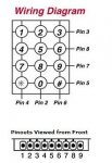
3x4 keypad

rob nash

Senior Member
hi,
I,ve got this keypad from tech supplies in front of me for some time now and am struggling to understand which is the column and rows i have added an row of pins so i can put it on a bread board am going to attach it to a 20x2 but i cant get of the starting block could anyone explain which pin is which
cheers rob
 

westaust55

Moderator
3x4 keypad schematic - wiring diagram

Seems that the 3x4 keypad connections are not quite so nicely in sequence as for the 4x4 keypads which I have used.

The atatched diagram may help further:
 

Attachments

Jamster

Senior Member
As i have so much time on my hands today, if you havn't already got code...
Code:
init:	SYMBOL keypress=b1
	'colums
	SYMBOL pin_4=pinB.0
	SYMBOL pin_2=pinB.1
	SYMBOL pin_6=pinB.2
	'rows
	SYMBOL pin_3=B.3
	SYMBOL pin_8=B.4
	SYMBOL pin_7=B.5
	SYMBOL pin_5=B.6
	
	
main:	for b0=0 to 3
		keypress=15
		if b0=0 then high pin_3 : endif
		if b0=1 then high pin_8 : endif
		if b0=2 then high pin_7 : endif
		if b0=3 then high pin_5 : endif
		
		if pin_4=1 then let keypress=1+(b0*3) : endif 
		if pin_2=1 then let keypress=2+(b0*3) : endif
		if pin_6=1 then let keypress=3+(b0*3) : endif
	next b0
 
Last edited:

westaust55

Moderator
Don't forget the use of a resistor matrix and a single ADC input to read the entire keypad.

Example code and resistor values exist in posts on this forum.
 

shellakaa

Member
gee am I glad my keypads were in sequence, I had no clue but I got it right by fluke (or maybe most are too easy) first time , that one would have given me a headache :)
 

rob nash

Senior Member
thank you all for the replies todays the day i get the this keypad working
jamster thanks for the code snip struggling to understand it at the moment am sure i will know a more by tonight cheers.
westaust55 the diagram was helpful, i have seen the threads on resistor matrix am checking my resistor box for the values,am little unsure about the placing of the resistor, but i have the attitude do it an see.shellakaa techs pic lock manual says keypads can be daunting at at first they were,nt joking glad u got yours up and running first time.


cheer rob
 

geoff07

Senior Member
It is down now.

For anyone not using an X1 or X2, you will have to recode jamster's expression to use left to right evaluation (i.e. no brackets).

As long as you have the pins free, software is cheaper than resistors! But don't forget the pulldowns on the input lines or they float and give random output.
 

MartinM57

Moderator
You can use brackets in X1 and X2 PICAXEs? (rhetorical question....answer is no, you can't use them on any PICAXEs)

I think Jammy forgot to add "untested" to his code example (and to tell us what PICAXE the code is for so the pin assignments work)...
 

Jamster

Senior Member
Tested in the simulator for the 20X2

Also "Marty" i think you should look at pg 23 of manual 2. You have been missing out.
 
Last edited:

Jamster

Senior Member
Interesting... although the manual says its possible, it dosnt pass syntax check on second test...

Anyway found a fatal flaw in the origianal code so here is an updated version:
Code:
init:	SYMBOL keypress=b1
	'colums
	SYMBOL pin_4=pinB.0
	SYMBOL pin_2=pinB.1
	SYMBOL pin_6=pinB.2
	'rows
	SYMBOL pin_3=B.3
	SYMBOL pin_8=B.4
	SYMBOL pin_7=B.5
	SYMBOL pin_5=B.6
	
	
main:	for b0=0 to 3
		keypress=15
		if b0=0 then high pin_3 : low pin_7,pin_8,pin_5 : endif
		if b0=1 then high pin_8 : low pin_7,pin_5,pin_3 : endif
		if b0=2 then high pin_7 : low pin_5,pin_8,pin_3 : endif
		if b0=3 then high pin_5 : low pin_7,pin_8,pin_3 : endif
		
		if pin_4=1 then
		let keypress=b0*3
		let keypress=keypress+1
		endif 
		if pin_2=1 then
		let keypress=b0*3
		let keypress=keypress+2
		endif
		if pin_6=1 then
		let keypress=b0*3+3
		let keypress=keypress+3
		endif
	next b0
	goto main
 
Last edited:

hippy

Technical Support
Staff member
As it's not been mentioned ... pull-down resistors.

Though I'd opt for using active-low logic, using pull-up resistors, and then the on-chip weak pull-ups can be used so nothing external needed.

I'd also have only one of the drive lines active at a time, the others as inputs so there's no risk at all of pressing multiple keypad buttons and shorting an output low to an output high.

There are then a number of improvements which can be made; a very quick check to tell if any keys are pressed so the whole pad doesn't need to be scanned if no keys pressed, and having three control lines and reading the four others back which can take advantage of reading the entire port, masking and using NCD to increase speed of scanning - Though that might not give key press codes which match what's wanted though.

The following code uses a 20X2 to read a 5 x 5 matrix which uses these technique ...

http://www.picaxeforum.co.uk/showpost.php?p=128741&postcount=5
 

westaust55

Moderator
The single ADC input method can be done in two ways:

1. A group of resistors in series as a form of potential divider with each switch connecting at a between two resistors and connected to ground. When a switch is closed, the signal point voltage varies due to the change in the potential divider. Cannot be used with a matrix type keypad. A single ADC input is used.

2. A set of resistors for both the rows and columns in a matrix along with another resistor to ground (0 Volts). The resistors are typically in a binary weighting scheme where each is approx twice the value of the previous resistor so that no two switch combinations result in the same resistances for the upper part of the potential divider. Can be used with a matrix type keypad. A single ADC input is used.

Both methods have been discussed on this forum and on other sites/books in the past.

There are some variants as well. BCJKiwi and manuaka have posted on such schemes:
http://www.lancer3.com/Files/ADC Keypad Schematic.pdf
http://www.picaxeforum.co.uk/showthread.php?t=7791
 
Last edited:

westaust55

Moderator
Tested in the simulator for the 20X2

Also "Marty" i think you should look at pg 23 of manual 2. You have been missing out.
Martin has not been missing out.
He, and others, have more likely read the Programming Editor Revisions document which states:
Programming Editor Revisions.

*** Known Restrictions
- #rem/#endrem must be used in lower case to correctly colour code
- Simulation 'Connect' feature not yet available
- X1 / X2 'let' mathematical equations cannot yet use brackets
*** End of known restrictions


5.3.4 Fixed issue with direct download of flowchart when using X2 parts with portB as outputs (e.g. when using motor direction)

:
:
:
 

geoff07

Senior Member
Too much to read. Pity, though I was going by the manual not experience.

I'm curious as to why only X parts can (in a latter version!) use brackets. That implies it is a function of the chip rather than quite 'easily' implemented in an optimising compiler. If it was done when parsing then any chip could have it. Is it a stack thing?
 

hippy

Technical Support
Staff member
"A stack thing" covers it without going into details. Support for brackets requires both compiler and firmware suppport plus memory for intermediate results. Prior to the X1 parts there wasn't such memory available.
 

rob nash

Senior Member
hello

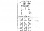
so far i failed at matrix scaning the keypad, having some success with the ADC appoarch i added a pic (a poorly done pic) of the circuit am using to get the adc readings. The choice of resistor was limited to what was in my box
the code is working BUT need help with inproving the code please.
Code:
symbol spk = b.5
symbol lcd = b.7
symbol key = w6
symbol junk = b8
init:
    pause 500
      serout Lcd,N2400,(254,128,"project picaxe       ")
	serout Lcd,N2400,(254,192," keypad  40x2         ")
	pause 1000
		serout Lcd,N2400,(254,128," hit my keys  ")          
	pause 1000
	serout lcd,n2400, (254,1)


do
 
 wait_for_keypress:
  readadc 0,junk
  if junk < 4 then wait_for_keypress
  pause 25
  readadc 0, key
  
  wait_for_release:
    readadc 0 , junk
    if junk > 5 then wait_for_release
    
   bintoascii key, b4, b3, b2, b1, b0
  serout lcd,n2400, (254,192, "key value", b2, b1, b0,"    ")
  pause 10
         
           if key = 193 then gosub one
           if key = 162 then gosub two
           if key = 121 then gosub three
           if key = 208 then gosub four
           if key = 173 then gosub five
           if key = 127 then gosub six
           if key = 177 then gosub seven
           if key = 151 then gosub eight
           if key = 115 then gosub nine
           if key = 203 then gosub star
           if key = 125 then gosub Hash
           if key = 169 then gosub naught


    loop


   one: sound spk, (10,50)
   pause 10
   serout lcd,n2400, (254,128, "   botton 0ne     ")
   pause 1000
   return
   
     two: sound spk, (20,50)
   pause 10
   serout lcd,n2400, (254,128, "   botton two     ")
   pause 1000
   return
   
   three:sound spk, (30,50)
   pause 10
   serout lcd,n2400, (254,128, "   botton three     ")
   pause 1000
   return
   
   four: sound spk, (40,50)
   pause 10
   serout lcd,n2400, (254,128, "   botton four    ")
   pause 1000
   return
   
    five: sound spk, (50,50)
   pause 10
   serout lcd,n2400, (254,128, "   botton five    ")
   pause 1000
   return
   
   six:sound spk, (60,50)
   pause 10
   serout lcd,n2400, (254,128, "   botton six   ")
   pause 1000
   return
   
   seven:sound spk, (70,50)
   pause 10
   serout lcd,n2400, (254,128, " botton seven  ")
   pause 1000
   return
   
     eight:sound  spk, (100,30)
   pause 10
   serout lcd,n2400, (254,128, " botton  eight ")
   pause 1000
   return
   
   nine:
      sound spk, (100,20)
   pause 10
   serout lcd,n2400, (254,128, " botton  nine  ")
   pause 1000
   return
   
   star:
   sound spk, (100,320)
   pause 10
   serout lcd,n2400, (254,128, " botton    *     ")
   pause 1000
   return
   
   hash:
   sound spk, (100,320)
   pause 10
   serout lcd,n2400, (254,128, " botton    #    ")
   pause 1000
   return
   
    naught:
   sound spk, (100,320)
   pause 10
   serout lcd,n2400, (254,128, " botton    0    ")
   pause 1000
   return

am thinking the if and gosub statements should not be the main loop but i just cant get my head around the statment needed to look up the value returned.
"the setup has changed am using a homebrew 40x2 board with a speaker and lcd (axe33).
hippy wht a master apiece thanks for sharing it gonna take me ten years to fully understand your code thoe.

cheers rob
 

Attachments

hippy

Technical Support
Staff member
if key = 121 then gosub three
if key = 127 then gosub six
if key = 125 then gosub Hash

You really want to compare key values to a range so that any noise from the ADC or differing keypad pressures don't cause keys to be missed or misread ( more likely with conductive rubber buttons against PCB tracking ).

You also want to achieve the widest spread as possible for each key so you can have a wide range to detect each key within and limit the chance of a key press being read as some other key.
 

westaust55

Moderator
The next thing you will find is that the value received from the READADC command will likely not be 100% consistent for each key but can vary by a few counts either way.

If you sort and look at key values you have:
if key = 115 then gosub nine
if key = 121 then gosub three
if key = 125 then gosub Hash
if key = 127 then gosub six
if key = 151 then gosub eight
if key = 162 then gosub two
if key = 169 then gosub naught
if key = 173 then gosub five
if key = 177 then gosub seven
if key = 193 then gosub one
if key = 203 then gosub star
if key = 208 then gosub four


As can be seen some are not very far apart. Adjusting resistors may improve that. But for now with the sorted list we can accommodate some tolerance by changing the values for the test and using less than rather than equals = something like:
if key < 117 then goto nine
if key < 123 then goto three
if key < 126 then goto Hash
if key < 131 then goto six
if key < 155 then goto eight
if key < 165 then goto two
if key < 171 then goto naught
if key < 175 then goto five
if key < 185 then goto seven
if key < 198 then goto one
if key < 205 then goto star
goto four

Notice that the gosub has been replaced with a goto which prevents other problems but also saves time on each loop as no testing of other values occurs once a match has been found.
 
Top