28x2 help...

I'm new to picaxe, but i have gotten other micros working (Propeller, Arudino) but i can't seem to get the 28x2 to work. I'm powering it with 5V and I'm using Sparkfun's 3.3V USB to Serial(3.3 Is logic high for 5 volts and I'm conditioning the TX from the picaxe). But the programming software doesn't detect it at all.

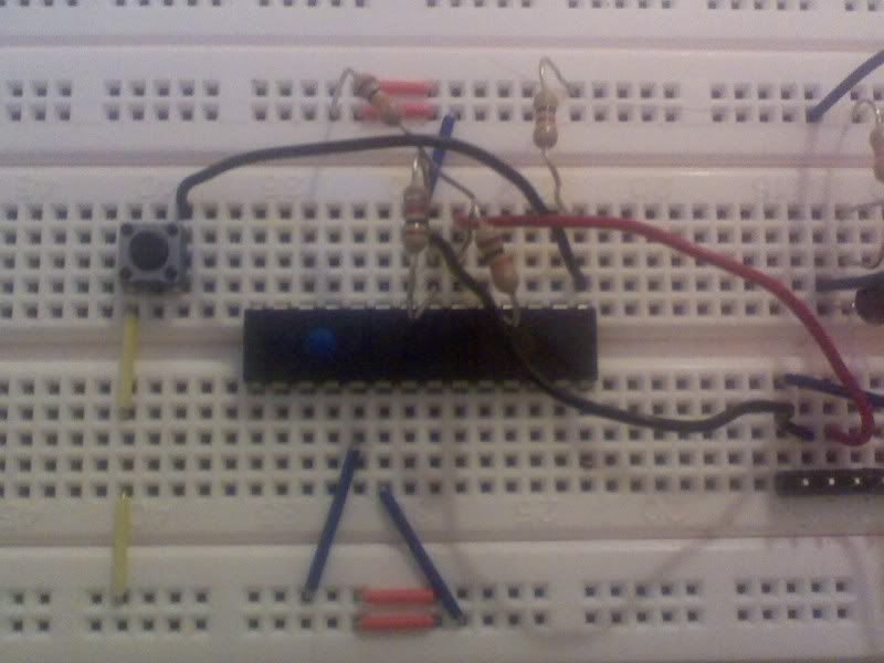
I'll post pictures if anyone requests them.

Also, Is there anyway to find out if the picaxe is functioning without the programming software (I.E the Arduino flashing a LED)

Thanks,
Matthew
 

Andrew Cowan

Senior Member
If you pull the serial in pin to V+, you should see some activity on the serial out pin.

That will confirm if the chip is working.

A
 
If you pull the serial in pin to V+, you should see some activity on the serial out pin.

That will confirm if the chip is working.

A
I wish i could see RX serial traffic, but somehow the USB-Serial is RX led is broken(Snapped Off?)

It's not sending any data back. (I used the terminal)

*Latest Update*
Seems like i made a wiring mistake, I put the wire AFTER the pull-up resistors. But i still can't program.
 
Last edited:

Technical

Technical Support
Staff member
Sparkfun's 3.3V USB to Serial(3.3 Is logic)
Check the polarity of the signal from this adapter - it may be inverted to what the PICAXE expects.
In the Programming Editor software see the View>Options>Serial Port>Test feature and follow the on-screen instructions.
 
Check the polarity of the signal from this adapter - it may be inverted to what the PICAXE expects.
In the Programming Editor software see the View>Options>Serial Port>Test feature and follow the on-screen instructions.
The led is off when the led on the serial test is on.
 

hippy

Ex-Staff (retired)
That does not look like the minimal download circuit to me; although not clear in the photograph it appears that the two resistors nearest the chip have both ends connected into the same breadboad tracks.

From the result of the Serial Port test it appears that the USB-to-Serial interface is putting out an inverted signal. That will require reprogramming the interface using MPROG.EXE from FTDI to invert the signals.
I added a resistor to the TX of the picaxe to condition the RX line for the USB-SERIAL.

So i need to reprogram the EEPROM to NOT invert the TX and RX signals or to invert?

*update*
I inverted the signal which means now when the test led is on the real led is on too.
 
Last edited:

hippy

Ex-Staff (retired)
Part of the main PICAXE code execution loop checks for a program download between statements ( and some like PAUSE check while executing ) so whenever the download is issued that is usually seen by the PICAXE and it commences download.

Some commands do not check for a download because of their timing requirements ( SERIN, SLEEP and so on ) so there may be times when an automatic download doesn't seem to work. If that happens the best approach is to do a Hard Reset; hold the PICAXE in reset or with its power off until the download window shows "Connecting to hardware ...". The first thing it does is check if there is a download so that should always work.
 
Top