24V AC to 5V DC

I want to hook my picaxe up to a thermostat controller to view which of six heater systems is on. The thermostat outputs 24V AC on one of six signal pins depending on the thermostat that is on. Is there a way to convert the 24V AC to 5V DC? Keep in mind I have to do it for six different signals so the simpler the better.
Thanks!
 
Last edited:

Dippy

Moderator
Have you been away??

Bridge rectifier, capacitor, 5V regulator, capacitor.
Get Data sheets for example capacitor values.
Total cost £1.50 or less if you use Fleabay.

Just be aware of power ; what will be the expected current at the 5V end?
You will have to check component values and ratings.
If you don't understand this, please ask back here.


Have a search on the World Wide Web for example circuits.
 

g6ejd

Senior Member
Two resistors in series with a diode in series with the PICAXE input so R1 to the 24V supply, the other end connected to R2, the other end to Gdn. At the junction of the two, either a diode in-series to the PICAXE inputs, or in reverse across R2, plus a small amount of smoothing capacitance should suffice, say 10uF as your thermostats are slow.
 

Armp

Senior Member
Resistor -> Diode -> (Capacitor+4.7V Zener in parallel) -> GND

But if your system is anything like mine I'd would (and did) pay a bit more and get optoisolators to keep the nasty relay spikes away from the PICAXE.
 

Dippy

Moderator
Aha, yes, the extra details make a difference.

In that case the optoisolator/coupler sounds good. I guess the grounds are separate too?
And then a bit of capacitance on the opto output side.
You can get AC optos which may help.


Anything more specific from us will probably require more details from you (i.e. the wiring).
 
So I would wire it
Resistor (what value) -> Diode -> (Capacitor(what value)+4.7V Zener in parallel) -> GND
Were would I connect the picaxe input pin?
The 24V AC would go into the resistor correct? I have trouble seeing how this would drop the voltage sufficiently..
 

Armp

Senior Member
So I would wire it
Resistor (what value) -> Diode -> (Capacitor(what value)+4.7V Zener in parallel) -> GND
Were would I connect the picaxe input pin?
The 24V AC would go into the resistor correct? I have trouble seeing how this would drop the voltage sufficiently..
The 24V goes to the resistor - I'd use a 1M resistor to limit the current to 35uA in case you accidentally connect it without powering on the PICAXE; and probably 0.1uF for the cap. The input to the PICAXE is the diode/cap/zener junction.

However before you do any of this let me see what we've got in the way of optoisolators - it's been a while...
 

SAborn

Senior Member
There is several ways to do this, but the best way is to use a optocoupler and keep both voltages independent of each other, and the cost wont be much more than a bridge rectifier, or a bunch of other stuff anyway.

Its a very simple circuit, and almost any optocoupler will do, the one in the schematic below is a darlington but it dont need to be.

Opto circuit.JPG
 

hippy

Ex-Staff (retired)
So I would wire it
Resistor (what value) -> Diode -> (Capacitor(what value)+4.7V Zener in parallel) -> GND
Were would I connect the picaxe input pin?
The 24V AC would go into the resistor correct? I have trouble seeing how this would drop the voltage sufficiently..
You would in effect be building a zener power supply which outputs 4.7V.

I wouldn't do it this way nor recommend it because you have to tie all 0V's of the zeners to 0V of the PICAXE and it's not clear where the 24V AC is derived from. You could be inviting serious problems in doing that.

To do it safely an opto which completely isolates each 24V AC from each other and the input would be recommended.

Added : See SAborn's post and circuit above.
 

premelec

Senior Member
build your own isolator!

Take an LDR and LED and run the LED through a resistor from the 24v and have that illuminate the LDR [wrapped in black tape or shrink wrap] and use the LDR signal to activate the PICAXE pin together with a pull up or pull down resistor... this way you'll learn more and accomplish what you want...
 

Armp

Senior Member
I want to hook my picaxe up to a thermostat controller to view which of six heater systems is on.
I wouldn't do it this way nor recommend it because you have to tie all 0V's of the zeners to 0V of the PICAXE and it's not clear where the 24V AC is derived from.
The typical US heating system has a single 24V transformer that provides all thermostats and control systems with 24V ac. This would include the micro based controller. In this case you can safely use simple R+C+diode circuits to minimise cost. And yes it is done....
 
Last edited:
There is several ways to do this, but the best way is to use a optocoupler and keep both voltages independent of each other, and the cost wont be much more than a bridge rectifier, or a bunch of other stuff anyway.

Its a very simple circuit, and almost any optocoupler will do, the one in the schematic below is a darlington but it dont need to be.

View attachment 9773
This seems perfect! Does everyone else agree that this will work?
 

SAborn

Senior Member
Nice thought Premelec, but do you really think for 25 cents its worth the effort, the led will cost that and ldr's aint cheap where optos are at 25c, you can even get packages with 4 optos in the same package, or just stack some singles into a 24 pin ic socket.
 

lbenson

Senior Member
Attached is a portion of a circuit I have not implemented using the LTV-814 (SFH620A on the schematic, which may not be an equivalent part, but seemed to have the right pinout). Not implemented, so any suggestions/corrections are welcome.
 

Attachments

Last edited:

SAborn

Senior Member
Basically any of these circuits will work, the one i posted is used on wind turbines to read the rpm from 2 phase wires, which is the same as your 24v ac, the circuit works well.

Any of the 4NXX range will do the job and they are easy to find, albeit they are a 6 pin package and pin 3 and 6 are not used, if you can find the 4 pin packages then they take up less board space, but often harder to find at your local supplier.
 

premelec

Senior Member
cheap or experience?

@SAborn - I have optoisolators, transformers, relays, PhotoMos relays, LDRs, and so many other parts - I use what's at hand [from 10s of thousands of salvaged and new parts] - the last time I used an LED LDR combination was to use a pedometer to count furnace cycling with a 24 volt gas solenoid being the signal so perhaps I was just reminded of this particular method... Whatever works and if speed & actual KV isolation etc are a big factor - that limits the parts that can be used... the first LDR + neon tube units I used were choppers and needed high speed [and there was a Faraday wire screen to prevent noise pickup from the switching neon lamps... [microvolt DC amps]. I hope E.G. is learning rather than just being told what to do. It's so easy to get too much information from the Internet without getting understanding or experience useful for eventual creative design. Anyhow I'm hoping we're all learning and having fun.... So far I've learned a lot in this forum even after so many years of electronic experience... and sometimes I too just want the answer and not the reason for it. [especially with arbitrary programing rules and notation :)]
 
There is several ways to do this, but the best way is to use a optocoupler and keep both voltages independent of each other, and the cost wont be much more than a bridge rectifier, or a bunch of other stuff anyway.

Its a very simple circuit, and almost any optocoupler will do, the one in the schematic below is a darlington but it dont need to be.

View attachment 9773
Would a standard 1/2W resistor work for R1 or should it be a high wattage?
 

premelec

Senior Member
Hi EG - I suggest assessing what parts you have and try something - there are so many ways for this to work - and it's good you are considering many methods as each has it's own features... the big thing is not to burn out any essential parts of the system you are connecting to - or causing a failure which results in a house full of frozen people & pipes... :) [BTW you'll find salvagable optoisolators in things like old computer power supplies... so many parts available from discarded electronic material - mostly still working].

With regard to resistors - ohm's law is your friend and a nasty smell indicates you've not calculated it right... practice practice practice with all ohm's law variations![and watts = IxIxR for instance].
 
Last edited:
I don't have many on hand parts so really anything I try will involve buying parts. I do have stuff like resistors and capacitors. Just optocouplers or rectifiers.
 
There a 6 different thermostats all controlled by a controller. I am going to hook a picaxe up to the controller and log which thermostat is turned on when. I will also have a RTC and a serial logger.
Ex. 6:16 12/12/2011 Heater 1: On Heater 2: Off Heater 3: On Heater 4: On Heater 5: Off Etc.
 

eclectic

Moderator
There a 6 different thermostats all controlled by a controller. I am going to hook a picaxe up to the controller and log which thermostat is turned on when. I will also have a RTC and a serial logger.
Ex. 6:16 12/12/2011 Heater 1: On Heater 2: Off Heater 3: On Heater 4: On Heater 5: Off Etc.
Are the thermostats in different rooms?
If so, how are you planning to send data?
 
They all arrive at the same room. After more research the optocoupler circuit is perfect and exactly what I need. Thanks guys!
So is 1/2W enough for R1?
 
OK, got more info (not actually my house)
24V AC across to wires when thermostat is OFF
0V when thermostat is ON.
So I want 5V when the thermostat stat is on and 0V when it is off or vise versa.
 

SAborn

Senior Member
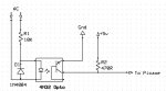
Yes 1/2 watt will do, but the circuit i gave will give you inverted data, 0V when thermostat is on, 5V when thermostat is off, but you should be able to deal with that in program.

Just remember most opto's are open collector and will require a pull up (or pull down) resistor, and as they are a isolated base device they can be used with either 5V+ or Ground supply.

The 470R resistor (pull up) in the circuit i gave, can be increased to 5k if you want to reduce the power loss through it, as it was only used as a low resistance to give a square edge wave for my purpose, as the output gets sloping edges with higher resistance on the pull up but this will not matter for your use.

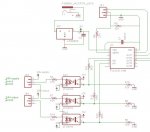
@premelec, i do very much agree with your view of learning and developing ones own devices, as well as working from the junk we have at hand, but for this application where EG needed 6 of these devices i seen it cheaper and neater to use discreet devices, its also a good learning curve for what a opto do, as they really are a handy device to isolate circuits. (every junk box should have a dozen of them)
 

pilko

Senior Member
@ lbenson. ---you do not appear to have a current limiting resistor on the input of the opto's in post 18.

pilko
 

lewisg

Senior Member
Optos are the way to go, I have used them several times to do just what you are attempting. The LED is on when the furnace, AC or fan is off depending on which contact you wire across. Just invert your logic to tell when the part of the HVAC is energized.

While I have not tried this with a PICAXE the problem I had with other controllers is the LED is flashing at 60 Hz and this caused the controller to see 60 switch pulses a second which was a problem. I ended up using a small resistor capacitor circuit on the photo side to smooth things out. If I can find a schematic I'll post it but it has been a few years and...

Maybe this isn't a problem with PICAXES but it sure was for Homevision, Phast and JDS home automation controllers.
 

SAborn

Senior Member
While I have not tried this with a PICAXE the problem I had with other controllers is the LED is flashing at 60 Hz and this caused the controller to see 60 switch pulses a second which was a problem.
Yes this is a very good point i had over looked, as the circuit given earlier was for counting the pulses, so one option would be use count to check the input pin and if the count was > 0 then the thermostat is on, if count = 0 then thermostat is off.
The other option would be to add filtering to remove the 60Hz.

Me i am lazy so would do it in code and use the count method.
 

Armp

Senior Member
This is what I use for my Heat Pump and Oil Furnace interface.
Yup - that's the basic solution. Perfectly adequate as long as the PICAXE and the 24V have a common GND.

I would suggest that if implemented as shown you would subject the LED to 34V reverse bias and it would not last very long...

I would move R2 upstream of C1, so that R2C1 form a low pass filter to help suppress spikes from relays etc.

Possibly make R2 and R3 10 times bigger (820K, 100K) if there is any possibility of applying 24V AC without having +5 on the PICAXE. You could of course then make C1 10 times smaller.

Note to self: figure out how to draw and attach quick schematics!
 

Dippy

Moderator
Can't you simply put an C//R on the opto output to effectively 'rectify' the AC switchy-offy-onny?
This will keep the output side above the TTL threshold and the R will discharge the cap when no AC, therefore drag it quickly below TTL threshold.
It will add a little delay into the system, but should make it a simple on/off detection rather than wrestling with frequencies.
 

Armp

Senior Member
OK, got more info (not actually my house)
24V AC across to wires when thermostat is OFF
0V when thermostat is ON.
That's correct - just remember if you 'accidentally' switch the thermostat to 'Cool' - then the thermostat action is reversed and it comes on when the temperature is above the desired setting. House gets hot quite quickly!

We have now implemented 'failsafe' digital thermostats that report the actual room temperature back to the controller rather than just OFF/ON. Then you can optimize your heating plant operation for varying outside temps.
 

hippy

Ex-Staff (retired)
This is what I use for my Heat Pump and Oil Furnace interface.
You could probably reduce that to just the one current limiting resistor ( perhaps also requiring a pull-down ). With the caveats already mentioned of 0V/ ground issues and the fact it will not be a static high signal when AC is present - the use of COUNT is a good solution to that.

For multiple inputs, a b0=0 and a few tight loops of -

b0 = b0 | pinsC

for 10ms+ would probably work.
 
Top