Hi everyone
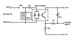
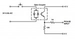
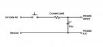
Is the attached method of input interfacing with a PICAXE chip valid?
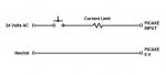
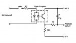
ooops forgot to put resistor in AC circuit
Is the attached method of input interfacing with a PICAXE chip valid?
ooops forgot to put resistor in AC circuit
Attachments
-
 26.6 KB Views: 92
Last edited:
")