20M2 to MAX7219 Drive 4 large Seven Segment

Jaden

Senior Member
Hi,

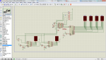
I am trying to drive 4 seven segment displays (7") with a MAX7219 from a 20M2. I can get the first segment to show a 'H' but the others will not switch on. Via PICAXE VSM (great program) I can see that they are getting the data, just not being switched on. I am using the C.0 to drive another two segments and would like not to use C.0. DO I need to be using the hserout or can I use the three that I have listed? This code is not mine but it will be easy for me (almost training wheels off) to be able to use it to get the four segments to count down minutes. This is my final goal.

I have four Comon Cathodes so I want to use them and not have to buy CA's.

Thanks
Jaden

Code:
' ================================== MAX7219_Countdown.bas =================================
' This program uses a PICAXE-20M2 to manually shift-out SPI data to
' a MAX7219 LED display driver. The 7219 is connected to a 4-digit,
' 7-segment LED display. The program displays the word "HELP"

' === Constants ===
' Hardware interface to the MAX7219
symbol sData = B.5 					' data out line to Max7219
symbol clock = B.7 					' clock line
symbol sLoad = B.6 					' pulse briefly to load data onto LEDs

' Register addresses for the MAX7219
symbol decode = 9 				' decode register; specify digits to decode
symbol brite  = 10 				' intensity (brightness) register; 15 = 100%
symbol scan   = 11 				' scan-limit register; specify # of LEDs
symbol on_off = 12 				' 1 = display on; 0 = display off

' === Variables =====
symbol outByte = b0 				' data byte to be transmitted to the LED
symbol maxReg  = b1 				' MAX register that receives the data byte
symbol forMax  = w0 				' 
symbol index   = b2 				' used in for-next loop

' === Directives ====
#picaxe 20M2 					' specify PICAXE processor

' ============================== Begin Main Program =============================

' Initialize MAX7219


maxReg = scan 					' set scan limit for digits 0-3
outByte = 3
gosub shout16

maxReg = brite 					' set brightness to 5 (15 = 100%)
outByte = 5
gosub shout16

maxReg = decode 					' set BCD decoding for digits 0-3 
outByte = 15
gosub shout16

maxReg = on_off 					' turn display on 
outByte = 1
gosub shout16

' Send data to the four digits
maxReg = 1 						' 1st LED from left = "H"
outByte = 12
gosub shout16

maxReg = 2 						' 2nd LED from left = "E"
outByte = 11
gosub shout16

maxReg = 3 						' 3rd LED from left = "L"
outByte = 13
gosub shout16

maxReg = 4 						' 4th LED from left = "P"
outByte = 14
gosub shout16
end

' ==================== End Main Program - Subroutines follow =====================
shout16:
for index = 15 to 0 step -1 			' MAX7219 requires a 16-bit word
	if bit15 = 1 then 			' set sdata to correspond to bit15
	  high sData
	else
	 low sData
	endif
	pulsout clock, 2 				' briefly pulse the clock line
	forMax = forMax * 2 			' shift char left for next MSB
next index

pulsout sLoad,2					'briefly pulse the load line
return
 

PaulRB

Senior Member
Jaden,

Nick's right - we need to see that circuit to be sure what's going on.

The max7219 can drive up to 8 digits x 8 segments, so not sure what you mean by "using C.0 to drive" 2 more segments. Maybe the circuit diagram will make that clear.

You don't want to be using hserout, its not that kind of "serial". B.5-B.7 will be fine. If you had a 20x2, you might want to use the hspiout, but 20m2 can only bit-bang. In this case bit-banging will be more than fast enough.

Max7219 will only drive common cathode displays, you have the right kind.

Reviewing your code... if you want to display letters rather than numerals, you should not be setting BCD decode on. I'm guessing the data you're sending does not make sense in BCD, hence displays not lighting up. Come to think of it, I don't understand how you are seeing the "h"!

Paul
 
Last edited:

westaust55

Moderator
At power up, the MAX7219 is reset and oh enables the first digit to display.

Have back in Dec 2012 been experimenting with this chip and a 4 digit display using several different PICAXE chips.
Not home right now to grab my version of code for you.

In addition to a schematic diagram as already requested, a clear photo taken perpendicular (at right angles) to the board may help others identify any wiring errors.

EDIT:
Definitely do not use the HSEROUT (and HSERSETUP) command(s).
You will need to bit bang when used with the M2 parts (X1 and X2 can use the SHIFTOUT for a ~4 times data transfer speed improvement).
There are ways to speed up the data transfer (at the expense of code size) but we can worry about those later once you have the project displaying all 4 digits.
 
Last edited:

Jaden

Senior Member
Sorry folks,

The story..

I am driving two futurlec large seven segment displays http://www.futurlec.com.au/Lg_LED_7_Segment.jsp . This is working from the C.0, C.1 & C.2 output of the 20M2. This is a count down clock from 30 seconds. I also want to drive 4 seven segments with the same chip, they are 4" (sorry not 8", yeah wait for the jokes ;) ). I am using the MAX7912 to drive these as it is able to drive the 4" segments quite happily. I was hopping to just use the 20M2 but I have heaps of room if I need to add another picaxe and split the buttons of to two different Picaxes. Just not sure how to get the MAX7912 controlled from the pins I need to use! BUT, I can use any other pins on the 20M2. As eventually I will also need to pause and run both clocks together it would be easier from the same chip using the ability it has to run two 'independent' programs. Please let me know if I am barking up the wrong tree.

I got this code from the Evil Genius PICAXE book and only can just follow it. The four segments I want to be able to count down from a given time, selectable from 8:00m to 2:00m and count down. The bottom line is I am making a 'shot' clock for water polo, this is the same as a basketball shot clock. The 30 second count down segments I have been helped by a few of you to get it up and running. I did have the words HELP up when i used a 08M2.

Thanks
shotclock.png
 

Attachments

Last edited:

westaust55

Moderator
Certainly nothing wrong with using the proposed three pins.

try additing the lines:
LOW SLoad
LOW Clock
LOW SData

or use the DIRSB command to first set the three pins low at the start of the program initialisation

That ensures all pins are outputs and pre-set to avoid garbage being seen by the MAX7219
 

westaust55

Moderator
Try adding a 10 uF tantalum or electro capacitor across the supply close to the MAX7219 as per the chip’s datasheet to avoid voltage fluctuations that may reset the MAX7219.
(Just a pity for you at least, that I have not posted my usual Getting Started "tutorial" for the MAX7219 - only partly written but matters here at Christmas time have delayed publication as it mentions such things as the capacitors and pull down resistors on clock and load lines).


EDIT:
Can you provide a link to those 7" 7-seg displays.

Looking at the Futurlec website at datasheets for 4” and 5” single 7-seg RED LED displays the forward volt drop is typically 9.25 Volts and max of 11 Volts. See for example: http://www.futurlec.com.au/LED/7SR50011AS.jsp
This suggests that a MAX7219 will likely have problems driving the LED’s fropm a 5 V supply as it can really only handle LEDs with up to 3.5 Volt forward volt drop on a 5 Volt supply.
 
Last edited:

Jaden

Senior Member
Re the caps and such, I have added these on my KiCad design, I have omitted some of these components on VSM as it does not effect the basic wireing design (??). The three lines I have going to the two 7" segemnts (heaps of LED's as shown in on the web page) actually connect to this board and not as shown in the VSM diagram, again, just to test the code. These displays are actually driven by a 12V rail and I think a ULN2008 onboard.


The 7" LED displays (two) is as per the link I have given, they have drivers and work OK with the program I have. The 4" Seven Segments are as follows http://www.nb-flying.com/pid11407251/400inch+single+digit.htm . I have NFD-40011ES-11 . I have designed a circuit with switching transistors from a 12V supply, hopefully I will not have to use them.


LOW SLoad
LOW Clock
LOW SData
This fixed it, thanks westaust55 . Very happy I can use those pins. In the Evil Genious book he did have dirsc = %10001111, I took this out as when I tried it on dirsB with the three pins on it did nothing!

(Just a pity for you at least, that I have not posted my usual Getting Started "tutorial" for the MAX7219 - only partly written but matters here at Christmas time have delayed publication as it mentions such things as the capacitors and pull down resistors on clock and load lines).
Where can we view these publications?

Final code for those that would like it with abouve circuit, don't forghet to add cap as westaust55 directed.

Code:
' ================================== MAX7219_Countdown.bas =================================
' This program uses a PICAXE-20M2 to manually shift-out SPI data to
' a MAX7219 LED display driver. The 7219 is connected to a 4-digit,
' 7-segment LED display. The program displays the word "HELP"

' === Constants ===
' Hardware interface to the MAX7219
symbol sData = B.5 					' data out line to Max7219
symbol clock = B.7 					' clock line
symbol sLoad = B.6 					' pulse briefly to load data onto LEDs

' Register addresses for the MAX7219
symbol decode = 9 				' decode register; specify digits to decode
symbol brite  = 10 				' intensity (brightness) register; 15 = 100%
symbol scan   = 11 				' scan-limit register; specify # of LEDs
symbol on_off = 12 				' 1 = display on; 0 = display off

' === Variables =====
symbol outByte = b0 				' data byte to be transmitted to the LED
symbol maxReg  = b1 				' MAX register that receives the data byte
symbol forMax  = w0 				' 
symbol index   = b2 				' used in for-next loop

' === Directives ====
#picaxe 20M2 					' specify PICAXE processor

' ============================== Begin Main Program =============================

' Initialize MAX7219

 LOW SLoad						' set B.5 (SLoad) low
 LOW Clock						' set B.7 (Clock) low
 LOW SData						' set B.6 (SData) low

maxReg = scan 					' set scan limit for digits 0-3
outByte = 3
gosub shout16

maxReg = brite 					' set brightness to 5 (15 = 100%)
outByte = 5
gosub shout16

maxReg = decode 					' set BCD decoding for digits 0-3 
outByte = 15
gosub shout16

maxReg = on_off 					' turn display on 
outByte = 1
gosub shout16

' Send data to the four digits
maxReg = 1 						' 1st LED from left = "H"
outByte = 12
gosub shout16

maxReg = 2 						' 2nd LED from left = "E"
outByte = 11
gosub shout16

maxReg = 3 						' 3rd LED from left = "L"
outByte = 13
gosub shout16

maxReg = 4 						' 4th LED from left = "P"
outByte = 14
gosub shout16
end

' ==================== End Main Program - Subroutines follow =====================
shout16:
for index = 15 to 0 step -1 			' MAX7219 requires a 16-bit word
	if bit15 = 1 then 			' set sdata to correspond to bit15
	  high sData
	else
	 low sData
	endif
	pulsout clock, 2 				' briefly pulse the clock line
	forMax = forMax * 2 			' shift char left for next MSB
next index

pulsout sLoad,2					'briefly pulse the load line
return
Now I will have a go at counting down.

Thanks once again.
 
Last edited:

westaust55

Moderator
This fixed it, thanks westaust55 . Very happy I can use those pins. In the Evil Genius book he did have dirsc = %10001111, I took this out as when I tried it on dirsB with the three pins on it did nothing!
Great to see/read that it is going.
Need to ensure all the pins are defined as outputs as you have discovered.


Where can we view these publications?
Most of my "Getting Started..." and other tutorials are posted in the finished projects area. The MAX7219 document is not yet posted as I have not completed compilation as a PDF yet - will be soon.

One way to track them down is:
1. Click on my ID (Westaust55) in the forum pages – eg at left of this post
2. Click on “View profile”
3. Click on “Find Latest Started Threads”
There are currently about 7 pages of threads started by me. Look mainly for those with “Getting Started…” or “Using the…” in the title.


When you have your project running, do a reset (cycle power) for the PICAXE only while the MAX7219 remains energised and watch the display.
You will likely get garbage on the LED display while the PICAXE restarts and until the IO pins become outputs and set low. The solution as already mentioned to ensure a known state is to add 10 kOhm resistors from the clock and load lines to ground.

If your are only using one MAX7219, then you can skip sending the first four most significant bits of data to the MAX7219 as they are not used and it saves some time in the bit-banged serial transmission routine.
This will not work if you cascade multiple MAX7219 chips as you need to push through the right number of bits (16) for each chip otherwise incorrect data passed to second and subseuqnet chips.
 

Jaden

Senior Member
Thanks westaust55, here is the final(ish) code with it counting down, may be useful to someone. In the final circuit I will have the resisitors and capacitors across power rails close to the chip as the data sheet says.
Some explination of what I want to achieve.....

- I have seperated each minute count instead of their own subroutine as I want the program to be able to start at any chosen minute value.
- I will eventually replace the
Code:
 pause 1000
with a loop to watch a button press, such as start, pause, stop and reset.
- After the countdown and the siren/digit flash it will park back at the beginning (chosen minute) waiting for a restart button.


Code:
' ================================== MAX7219_Countdown.bas =================================
' This program uses a PICAXE-20M2 to manually shift-out SPI data to
' a MAX7219 LED display driver. The 7219 is connected to a 4-digit,
' 7-segment LED display. The program displays the word "HELP"

' === Constants ===
' Hardware interface to the MAX7219
symbol sData = B.5 					' data out line to Max7219
symbol clock = B.7 					' clock line
symbol sLoad = B.6 					' pulse briefly to load data onto LEDs

' Register addresses for the MAX7219
symbol decode = 9 				' decode register; specify digits to decode
symbol brite  = 10 				' intensity (brightness) register; 15 = 100%
symbol scan   = 11 				' scan-limit register; specify # of LEDs
symbol on_off = 12 				' 1 = display on; 0 = display off

' === Variables =====
symbol outByte = b0 				' data byte to be transmitted to the LED
symbol maxReg  = b1 				' MAX register that receives the data byte
symbol forMax  = w0 				' 
symbol index   = b2 				' used in for-next loop
symbol y = b3
symbol x = b4
symbol z = b5

' === Directives ====
	#picaxe 20M2 					' specify PICAXE processor

' ============================== Begin Main Program =============================

Start:


' Initialize MAX7219

 	LOW SLoad						' set B.5 (SLoad) low
 	LOW Clock						' set B.7 (Clock) low
 	LOW SData						' set B.6 (SData) low

	maxReg = scan 					' set scan limit for digits 0-3
	outByte = 3
	gosub shout16

	maxReg = brite 					' set brightness to 5 (15 = 100%)
	outByte = 5
	gosub shout16
	
	maxReg = decode 					' set BCD decoding for digits 0-3 
	outByte = 15
	gosub shout16

	maxReg = on_off 					' turn display on 
	outByte = 1
	gosub shout16

'==========================start countdown===============================


time9:

' Send data to the four digits
	maxReg = 1 						' 1st LED from left = "BLANK"
	outByte = 15
	gosub shout16

	maxReg = 2 						' 2nd LED from left = "9"
	outByte = 9
	gosub shout16
	
	maxReg = 3 						' 3rd LED from left = "0"
	outByte = 0
	gosub shout16

	maxReg = 4 						' 4th LED from left = "0"
	outByte = 0
	gosub shout16


	Pause 1000

time8:


	maxReg = 2 						' 2nd LED from left = "8"
	outByte = 8
	gosub shout16
	gosub seccount

time7:
	maxReg = 2 						' 2nd LED from left = "7"
	outByte = 7
	gosub shout16
	gosub seccount
	
time6:
	maxReg = 2 						' 2nd LED from left = "6"
	outByte = 6
	gosub shout16
	gosub seccount
	
time5:
	maxReg = 2 						' 2nd LED from left = "5"
	outByte = 5
	gosub shout16
	gosub seccount
	
time4:
	maxReg = 2 						' 2nd LED from left = "4"
	outByte = 4
	gosub shout16
	gosub seccount
	
time3:
	maxReg = 2 						' 2nd LED from left = "3"
	outByte = 3
	gosub shout16
	gosub seccount
	
time2:
	maxReg = 2 						' 2nd LED from left = "2"
	outByte = 2
	gosub shout16
	gosub seccount
	
time1:
	maxReg = 2 						' 2nd LED from left = "1"
	outByte = 1
	gosub shout16
	gosub seccount
	
time0:
	maxReg = 2 						' 2nd LED from left = "BLANK"
	outByte = 15
	gosub shout16
	gosub seccount
	
'==========================sound siren & flash segments==========================
	
	for z = 1 to 4step 1
	  maxReg = 1 					' 1st LED from left = "0"
	  outByte = 0
	  gosub shout16

	  maxReg = 2 					' 2nd LED from left = "0"
	  outByte = 0
	  gosub shout16
	
	  maxReg = 3 					' 3rd LED from left = "0"
	  outByte = 0
	  gosub shout16
								
	  maxReg = 4					' 4th LED from left = "0" 
	  outByte = 0
	  gosub shout16
	
	pause 250						' make segments flash
	
	  maxReg = 1 					' 1st LED from left = "BLANK"
	  outByte = 15
	  gosub shout16

	  maxReg = 2 					' 2nd LED from left = "BLANK"
	  outByte = 15
	  gosub shout16
	
	  maxReg = 3 					' 3rd LED from left = "BLANK"
	  outByte = 15
	  gosub shout16

	  maxReg = 4 					' 4th LED from left = "BLANK"
	  outByte = 15
	  gosub shout16
	
	pause 250
	
	next z
'==================================End Of Siren==================================

goto start							' go back and do it again!

' ==================== End Main Program - Subroutines follow =====================


seccount:
	for y = 5 to 0 step -1
	maxReg = 3
	outbyte = y
	gosub shout16
	
	for x = 9 to 0 step -1
	maxReg = 4
	outByte = x
	gosub shout16
	pause 1000
	next b4
	next b3
	return
	
shout16:
	for index = 15 to 0 step -1 			' MAX7219 requires a 16-bit word
		if bit15 = 1 then 			' set sdata to correspond to bit15
	 	 high sData
		else
	 	low sData
		endif
		pulsout clock, 2 				' briefly pulse the clock line
		forMax = forMax * 2 			' shift char left for next MSB
	next index

	pulsout sLoad,2					'briefly pulse the load line
	return
 

Jaden

Senior Member
Is there a way to display other characters at all? That is characters that can be made up on a seven segment display?
 

westaust55

Moderator
Is there a way to display other characters at all? That is characters that can be made up on a seven segment display?
Yes.
For the digits 0-9 and letters “HELP- ” you are using the decoding to Code B.
If you turn of the decoding then the data for each digit you can send an 8-bit value to bring on the LED segments in any combination you wish.
There is a table in the MAX7219 datasheet which gives the correlation between the data value bits and the LED segments (A to G and dp)
I have used this technique to have a routine for counting in hexadecimal which required the additional characters “AbCdEF”
 

PaulRB

Senior Member
Jaden,

Here's my subroutine for sending data to max7219, if its useful. Probably faster than the one you're using now, but not sure speed is much of an issue anyway!

Code:
send7219: 'Send contents of w0 to the MAX7219 Driver IC

	pulsout M7219CLK, 1 'Bits 15 to 12 are not used
	pulsout M7219CLK, 1
	pulsout M7219CLK, 1
	pulsout M7219CLK, 1
	M7219DATA = bit11 : pulsout M7219CLK, 1 'Bits 11 to 8 are the command
	M7219DATA = bit10 : pulsout M7219CLK, 1
	M7219DATA = bit9 : pulsout M7219CLK, 1
	M7219DATA = bit8 : pulsout M7219CLK, 1
	M7219DATA = bit7 : pulsout M7219CLK, 1 'Bits 7 to 0 are the data
	M7219DATA = bit6 : pulsout M7219CLK, 1
	M7219DATA = bit5 : pulsout M7219CLK, 1
	M7219DATA = bit4 : pulsout M7219CLK, 1
	M7219DATA = bit3 : pulsout M7219CLK, 1
	M7219DATA = bit2 : pulsout M7219CLK, 1
	M7219DATA = bit1 : pulsout M7219CLK, 1
	M7219DATA = bit0 : pulsout M7219CLK, 1
	pulsout M7219LOAD, 1
	return
Here are the symbol definitions. I was using an 08m2 in this case, but almost any pins could be substituted.

Code:
'Pins for serial communications with the MAX7219 IC
symbol	M7219DATA = PinC.0
symbol	M7219CLK = C.4
symbol	M7219LOAD = C.1
I too forgot to set the 3 pins to outputs and to low at the start of my code, but I got away with it for some reason! I still don't understand how your code got the "H" to display and nothing else.

You are not short of pins on the 20m2, so its probably not worth changing the design, but... I was wondering if you could daisy-chain the 2 large displays to the 4 small displays, using the Dout pin on the max7219? There's no data sheet for the large displays on the link you posted, so its not clear if the signals are compatible (I noticed a not-gate on your schema for example). This would save 3 pins by using the same 3 to send data to all 6 digit displays.

Paul
 
Last edited:

westaust55

Moderator
@PaulRB,
For even greater (well slight) speed improvement with a single MAX7219, you can remove those first four PULSOUT commands.
 

PaulRB

Senior Member
@PaulRB,
For even greater (well slight) speed improvement with a single MAX7219, you can remove those first four PULSOUT commands.
Thanks Westy, I see you're right, as long as I'm not using the Dout to feed some other circuit (which I wasn't).
 

Jaden

Senior Member
Thanks for that code PaulRB, Will give it a go latter, I am fairly happy with what I have and as you have said speed is not an issue with what I am doing.
westaust55, thanks as well I would like to do a fancy letter scroll at the end of the game that would scroll letters across the four segments. As I am multitasking the 20M2 I am also happy to run the 30 second count down from a different program. The complication comes in when a game can be run as say 7 minutes or 7 minutes with start and stops in the match time, multitasking in the one chip allows me to send one button press high to both programs!

Thanks for getting this up and going, it is a lot less than I am using for the 30 second 'bit bangging' count down.

For those that are interested I have attached the documentation that came with the large digit, they come preassembled (with one LED arss about!)

Futurlec ET-7LSD

View attachment ET-7LSD Manual.pdf

http://www.futurlec.com.au/Lg_LED_7_Segment.jsp

You cannot buy the components for that much! If you are willing to wait for the slack delivery they have, you can get some cheap bits.
 
Top