20m + Lcd?

nickwest

Member
So far I've had my 44780-compatible LCD working in the following setups:

Serial firmware from www.oatleyelectronics.com
18X-driven parallel operation as in the picaxe manual
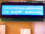
14M-driven parallel operation as per Hippy's elegant code at http://www.picaxeforum.co.uk/showthread.php?p=67665

However I'm completely stumped when I try to get the LCD to work with a 20M. I've tried Hippy's code as per the 14M above, I've tried the code from the manual, no luck. Why would the 14M code not work with a 20M, with output pins 0 to 5 connected as per the 14M?

I notice that when I "simulate" the program on on the 20M all 8 pins have data going out - is it all relevant? Which 6 pins of these 8 actually contain the required data for the LCD?

Has anyone got an LCD to work with a 20M?

Oh and I just re-connected the 14M to my circuit to make sure I hadn't fried the LCD. It still works fine. With the 20M back in place, all I get is the top line filled with black squares, regardless of what program I am running on the 20M. I think this means the LCD is not even being initialised by the 20M?

Thanks for your help.

Nick.
 

inglewoodpete

Senior Member
You mention serial firmware from Oatley, then go on to refer to 8-bit parallel connection. I'm not sure which setup you are using on the PICAXE.

I have a K221 - SERIAL LCD INTERFACE KIT from Oatley driving a surplus 2x16 character display (also from Oatley but now discontinued). I can confirm that the serial interface works well. (3 wires, 1 PICAXE pin: 0v, +5v and TTL serial data)
 

nickwest

Member
When I first got the LCD and started experimenting, I used the serial firmware chip, just to make sure that everything was working. Baby steps.

Now the serial firmware is put away in a drawer and I am using a 4-bit (6 wire) direct parallel connection from the picaxe to the LCD. So far I have had a 14M and an 18X working with the direct connection, but no success with the 20M.

Hope that explains it a bit better.
 

inglewoodpete

Senior Member
Aha! Now I'm catching up.

When you have problems like this, slow things right down.

Put long pauses (Eg 10 seconds or longer) between output statements so that you can use a logic probe or LED+Resistor (or several) to see that the right things are happening.
 

hippy

Ex-Staff (retired)
However I'm completely stumped when I try to get the LCD to work with a 20M. I've tried Hippy's code as per the 14M above, I've tried the code from the manual, no luck. Why would the 14M code not work with a 20M, with output pins 0 to 5 connected as per the 14M?

I notice that when I "simulate" the program on on the 20M all 8 pins have data going out - is it all relevant? Which 6 pins of these 8 actually contain the required data for the LCD?
I'd have expected either the 14M or original 18X code to have worked without change on the 20M though the connections would be different.

For the the original 18X, pins 4,5,6,7 are data bus for the LCD, pins 0,1 the control signals.

For the 14M, pins 2,3,4,5 are data bus for the LCD, pins 0,1 the control signals.

The code in the PICAXE Manual 3 will only work when wired as per the 18X.

It sounds like you may have a mis-wiring on your pins.
 

westaust55

Moderator
14M only has outputs 0 to 5, whereas larger chips have 0-7
Hippys code needs a tweak to make it more universal so as not to act upon the extra pins (outputs 6 and 7) of larger PICAXE chips.

change the subroutine SendDataByte as follows (see text in red):
Code:
SendDataByte:

        pins = bite / $10 * 4 | rsbit [COLOR="Red"][B]AND $3F  [/B][/COLOR]; Put MSB out first
        
        PULSOUT E,1                     ; Give a 10uS pulse on E
        pins = bite * 4 | rsbit [COLOR="red"][B]AND $3F  [/B][/COLOR]    ; Put LSB out second 
        PULSOUT E,1                     ; Give a 10uS pulse on E
        
        rsbit = RSDATmask               ; Send to Data register next


        RETURN
 

hippy

Ex-Staff (retired)
The change needs to be more subtle than that; left to right maths means the data nibble is in bits b7..b4 and the AND $3F zeroes the top bits :)

As the 20M has 8 outputs it should run either the 14M code ( using outputs 0-5 ) or the 18X code ( using outputs 2-7 ) without change providing the LCD is wired to the correct pins.

The 14M code should also run without change on an 18X ( using outputs 0-5 ).

The issue seems to me to be a simple miswiring, pin crossover problem, though I haven't tested LCD control on a 20M.

It is not possible to drop a 20M into a circuit configured for a 14M ( with bottom six legs hanging out the socket ) and have the 14M LCD code work as is because the output pin numbers are offset by one ( Serial Out is separate to Output 0 on the 20M ).
 

nickwest

Member
I'm pretty sure my wiring is correct. Attached are a couple of photos just in case. [19.5k maximum file size?? Hope they come out OK!]

the 14M and the 20M are running identical code, from Hippy's example. I have to confess I don't 100% understand it all - I know what each routing <i>does</i> but bitwise OR operations are not the sort of thing I could make for myself!

I'm wondering if maybe the timing for the 20M could be sufficiently different that the LCD isn't getting the right data at the right time?

Westaust55's modifications definitely take the data off pins 6 & 7, but I don't know enough to tell if the correct bits remain. Can anybody recommend a good guide to computer logic? I think I need to educate myself a bit here about the intricacies of the code!

NB: I have tried the 18X code also, using output pins 2-7 of the 20M. No success there either.
 

Attachments

westaust55

Moderator
The change needs to be more subtle than that; left to right maths means the data nibble is in bits b7..b4 and the AND $3F zeroes the top bits :)
The *4 only moves the byte variable data 2 bits not 4. :)
for the hi nybble, you divide by $10 (16) which moves it down to the low nybble then *4 to move it back up (left) 2 bits.
Then the low nybble is moved two bits to bits 2,3,4 and 5.
Keep in mind 14M does not have output pins 6 and 7.
bits 0 and 1 are for control.

Yes, I was masking the top 2 bits off :) - fully intended
since they were not used but the code does change them.
As you say the code will work on any PICAXE but is leaving "garbage in the top two bits and nickwest had specifcially commented that the LCD code was also causing the top bits to be changed.
 
Last edited:

westaust55

Moderator
here is a revised but untested version of the same subroutine for the 20M that will (hopefully) keep the status on ouputs 6 and 7 unchanged.

Maybe set the outputs high and see if they remain unchanged as a test.
So, give it a try and let us know if it does want is intended (I do not have a 20M to try it with).
the green text are the changes and extra lines


Code:
[COLOR="Green"]SYMBOL hibits = b10[/COLOR]

SendDataByte:
         [COLOR="green"]peek $06, hibits [/COLOR]; get port B GPR value
         [COLOR="green"]hibits = hibits * 2 AND $C0  [/COLOR]; we want port B bits 5 and 6 ready to go to out put pins 6 and 7
;        
                
        pins = bite / $10 * 4 | rsbit [COLOR="green"]AND hibits  [/COLOR]; Put MSB out first and retain stauts of top 2 bits
        
        PULSOUT E,1                     ; Give a 10uS pulse on E
        pins = bite * 4 | rsbit [COLOR="green"]AND hibits      [/COLOR]; Put LSB out second  and retain stauts of top 2 bits
        PULSOUT E,1                     ; Give a 10uS pulse on E
        
        rsbit = RSDATmask               ; Send to Data register next


        RETURN
 

hippy

Ex-Staff (retired)
I'm pretty sure my wiring is correct. Attached are a couple of photos just in case.
I cannot see anything wrong in the wiring so unless there's a broken wire which by luck works with the 14M but not the 20M, or there are some dodgy breadboard connections which only come into play when using the 20M, I would say your hardware was correct.

You could use some test code to toggle individual I/O lines and check they are toggling at the other end of the wire ...

Do
pins = b0
Pause 125
b0 =b0+1
Loop

The LCD is the same in each case so its initialisation code will be the same, and I cannot see anything in the code which will not work with a 20M. There's nothing about the 20M which would make the code flawed.

I have to admit that it's a mystery to me why it doesn't work.
 

hippy

Ex-Staff (retired)
Connected an LCD up to a 20M, ran the 14M code unchanged and "it just worked". I would suspect you have a hardware problem.

You say you have a "44780-compatible" not an actual 44780; there may be some subtle differences in timing though I wouldn't have expected that, and my LCD is on the end of a 45cm ribbon cable. It may be worth changing the "PAUSE 15" to "PAUSE 100" and the "PULSOUT E,1" to "PAUSE 10:pULSOUT E,10:pAUSE 10" to see if that gives any improvement.

Make sure your power supply is 5V.
 

nickwest

Member
The LCD is from Dick Smith Electronics in Australia www.dse.com.au, catalogue number Z4170.
The data sheet that came with the LCD says it uses a Samsung KS0066 controller which is "identical to the Hitachi 44780" however the online descriptions says the KS0066 is "similar to the Hitachi"

I've checked the inputs to the LCD using an LED across the outputs of both the 14M and the 20M. The PAUSEs suggested by Hippy and others helped here!

It's good to be able to see the data coming out of the picaxes. The 20M give a different pattern from the 14M. On the 14M, DB4-DB7 flicker merrily as the code runs, and the strobe on pin 1 is very obvious. On the 20M, I get lots of flickering on DB4, but only one very brief flash on DB5, and two flashes on DB6 & DB7. To me this suggests that not all the data is being sent. It is definitely not what happens in the Programming Editor's simulation. Everything looks fine in the simulator.

I've checked each output pin using the "PINS =" command and an LED to make sure none of the pins are individually damaged, and each one lights up just fine.

So from the above, I think I can safely say that the 20M is not running the code exactly the same way as the 14M.

The Programming editor (V.5.2.4, under windows XP) says I am using Firmware version 3.A (20M firmware version A). Hippy, is this different from the 20M you tried?

Westaust55, at this stage I am just trying to get the 20M to work, the extra pins are not so much of a concern. Running the code shows no difference to the pin behaviour. As I'm sure you're aware, it won't simulate correctly with the non-standard PEEKs. I get no flashes on pins 6 & 7 using Hippy's unmodified code - as i said above this indicates ot me that not all the data is getting sent anyway.

I've tried this with a couple of 20Ms (all with the same firmware) and have the same results.

does anybody have any further suggestions? For now I'm trying to make a program to initialise the LCD using nothing but "PINS = " and PAUSEs. As a program it's not very compact or efficient, but it might help me figure out just where the problem is. Has anybody tried this before?

I hope the above made sense, please let me know if there's anything I can clarify. Thanks to everyone for taking the time to read the thread so far and make suggestions!

PS. I also found a useful java-based 44780 simulator and some other 44780 info at http://www.deneyseti.com/dinceraydin/lcd/index.html
 

hippy

Ex-Staff (retired)
I'm sure others have the KS0066 working, and you have it working with the 14M.

I'm using 20M firmware 3.B. The revision.txt file indicates 3.B fixed issues with READ and PULSOUT but I'm not sure what those issues were. Either of those could be affecting the code.

Replacing the FOR-NEXT loops using READ with sequences of "bite=$xx" and replacing PULSOUT E with HIGH E:LOW E would remove those from the equation.
 

nickwest

Member
Hippy, you're 100% correct - LCD routines without READ and PULSOUT do work. This is an enormous relief for me!

Right now it's just throwing a couple of "T"s (for "test") on screen because I can't figure out how to put a long string into memory without using EEPROM and READ. It should be obvious by now that software is not my forte!

My changes to the example routines in the manual, based on your advice, are below. I still haven't got the Compact Hippy Routines working because I'm too thick today to work out how to do it without READ.

Thanks again, it's brilliant just to get _anything_ on the LCD!
 

Attachments

Last edited:

hippy

Ex-Staff (retired)
Here's the original 14M code modified to use LOOKUP rather than READ. I don't have real hardware to test it on at the present ...
 

Attachments

rbwilliams

New Member
Hippy,
I could not get a longer string with the 14M LCD code youposted a while back that used EEPROM.

But, now this is no longer an issue with this revised code using LookUp!

You are a genius!

Thanks!!!!
 

Attachments

Last edited:
Top