2 way link with control???

boelle

Member
Hi

I'm trying to figure out if it is possible to collect data from a remote location and send commands the other way ie read temps etc and then if needed activate a relay

What i had in mind was a 08m at the remote end collecting data and send them via a 433 mhz wireless link to a basestation that displays the collected data, the base station should also hold a switch that could activate a relay at the remote end.

Getting the temps etc one way to base stations is simple enough, plenty of examples on that... its more to get the command for the relay the other way that are the trouble, for me at least
 

manuka

Senior Member
This is quite PICAXEable using simple coding and 433 MHz gear (over modest distances). However of course you will need a transmitter & receiver (or transceiver) plus power supplies at each end. What is your budget? Distance? Environment ? Application?

A potential concern may relate to false triggering causing the remote relay to activate unreliably. If you're using this for anything serious (greenhouse heating etc) then extensive thought and trials may be needed... Stan.
 
Last edited:

boelle

Member
The distance is arround 50 meters or so, one end is a car where i want to collect the cabine temp and battery voltage plus control a relay that activates the engine preheater (webasto fuel burner thing) if possible also collect staus if the heater is running.

the first 2 are simple enough, and the status of the heater is a logic high/low signal, dont know if the line is 12V or 5V, but i know its a simple line that goes on when the heater is running (ie if the status on the clock/control unit is lit or not)...

Getting those 3 to a base station inside should be simple enough

but how do i send a signal to the car so that i can activate the relay?

to make sure signals go through without faults i have in mind to add ABC before and after the values ie ABC,12,20,1,ABC = 12 Volts - 20 Degrees - Heater Running.. so the base station has to check that it gets ABC both before and after, if not it should drop the readings and wait for another sequence.

the same could be used the other way, thou its more simple, it only have to send abc,1,abc ie 1 or 0 to tell if the relay should be on or off

as for the fuel burner it has its own control unit that takes care of safety. and i have spent many hours fault finding, the unit is so safe that even a flame sensor with 2 wires connect wrong will cause the unit to shut off the heater. so that one is not my concern
 
Last edited:

manuka

Senior Member
Yikes- engine pre heating ! Down under here in the balmy Southern Seas we tend to forget about the approaching European winter. Is this heater in the garage or under the bonnet in the engine bay? Petrol or diesel engine? How is the receiver to be powered- from the car battery? What fuel- kerosene? Your pattern of driving usage- short trips?

At first pass I'd not be at all happy about controlling a fuel burner for such needs by simple PICAXE/433 MHz techniques I'm afraid. Engine pre heating is not a Kiwi need,as even outdoor frosts are rare here (refer pix below for the only such event this past winter!). It's probably best someone used to these devices gives you advice, as I can only speculate about issues that may arise. Googling shows the likes of this. Stan.
 

Attachments

Last edited:

boelle

Member
hehe, i live in denmark and the temps have been droping like a stone for the past months so there is more to come

The heater is going to be mounted in the space between the front bumber and wheel arch, the car is a peugeot 207 '08. There is no risk in running the thing via a relay, webasto uses the same approach for their remote control, only this cost almost the same as the heater and provides no feedback. the thing is so made that should the heater get to hot (above 78 degrees C) it will shut off, and there is even a thermo switch that pops if the first limit fails. also the unit will go of if battery volts go too low. it works by sucking fuel from the tank via a combined pump/valve that requires pulses to make it work, ie if the unit dies and send a constant 12V the pump will stop and shut off fuel and the burner dies. So i will have no bad sleeps over using a relay to turn on the thing. I have all the manuals for the heater so that i can service and repair it. even got the stuff that workshop seller has.

It might sound like a dangerous thing to install but when you first understand the thing it's so simple and safe that you dont belive it.

once the burner has a flame that is used to heat up the cooling water that runs arround the flame chamber driven by a small electrical pump

the part in the car is going to be powered from the battery.
 

boelle

Member
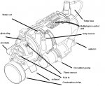
just for the fun of it a quick drawing of the heater, only stuff you dont see here is: control box, relay to turn on cabin fan once water is about 50C so that the windows are de-iced and cabin warm, control clock to turn on heater at 2 preset times and turn on the heater at once and lastly the dose pump mounted near the tank. The drawing was done by memory but i checked it and i got it right
 

Attachments

Last edited:

boelle

Member
Forgot my patterns of driving.. many short trips where the engine does not get relly warm for enough periods.

The benefit of installing the heater is that the sales value stays up as cold starts are prevented thus less tear on the engine.

My local seller for the heater are not even able to repair the unit as its an rather old one and they dont have staff trained for it, so i had to do that myself the hard way. This also means that when i need parts i have to give them the part number. but the thing about remote control is the same for never units, just a relay that turns the heater on and the heaters own control box takes care of the rest.

only thing i can think of are if the relay just needs to pulse to turn on the unit or if the heater goes of as soon the relay goes of... but well not the bigger problem.
 

graynomad

Senior Member
Getting those 3 to a base station inside should be simple enough
The relay control then is just the same thing but in reverse. Duplicate the receiver and transmitter (or use transceivers) and to stop clashes have the incar unit only transmit data after it's received a command.

That command can have the relay on/off as part of it.

So you send ABC,1,ABC as you said, and the remote unit responds with ABC,12,20,ABC.

I might also build in a timeout feature whereby the remote unit turns off the heater every (say) minute unless told otherwise. That way if the control unit dies or some interference totally screws the comms link the heater doesn't continue regardless. Not that that probably matters as I'm sure it has it's own safeguards, it just seems more "right". You would have to build in some hysterisis though because I doubt those heaters like being cycled on/off 10 times a second :)

Alternatively (and more simply), if you are within earshot, have the control unit emit an alarm of it doesn't get a response after 3 tries.

Re the cold mornings, I feel your pain, why just the other day it got down to 28C over night here. Brrrrr.
 
Last edited:

boelle

Member
using transceivers seems the way i will go,

but how could a sample code look like to get the relay command to the car? just learning here by looking at other peoples code
 

boelle

Member
Code for the unit in car, need a few tweaks - it comes from a rain water tank project ( http://kayno.net/2010/02/11/wireless-picaxe-based-water-tank-level-sensor/ ):

Code:
symbol tank_reading = w0
symbol cell_reading = w1

symbol tank_level = w2
symbol cell_mV = w3

symbol sensor_circuit_pin = 7
symbol tank_sensor_pin = 1
symbol tank_cell_pin = 0

symbol tank_min_reading = 204
symbol tank_max_reading = 610

symbol sleep_period = 52 '~120 seconds
 
main:

	'turn on sensor, transmitter
	low sensor_circuit_pin
	
	'pause to allow things to power up
	pause 5
	
	'read and transmit data
	gosub transmit
	
	'turn off sensor, transmitter
	high sensor_circuit_pin 
	
	'sleep until next time
	sleep sleep_period

	goto main

transmit:
	'read tank sensor
	readadc10 tank_sensor_pin,tank_reading

	if tank_reading < tank_min_reading then
		tank_level = 0
	elseif tank_reading > tank_max_reading then
		tank_level = 100
	else
		tank_reading = tank_reading - tank_min_reading
		tank_reading = tank_reading * 100
		tank_level = tank_reading / 410
	endif

	'read AA cell
	readadc tank_cell_pin,cell_reading
	
	cell_reading = 25600 / cell_reading '256 (8 bit adc resolution) * 100 
	cell_mV = 50000 / cell_reading '500 (mV of Vcc) * 100

	'transmit data
	serout 3,N2400,(85,85,85,85,"ABC",tank_level,cell_mV)
	
	sertxd("transmitted: ",#tank_level,":",#cell_mV,cr,lf)
	
	return
 

boelle

Member
tweaked the code, can any see errors?
input1 is the logic sense if the heater is running or not

Code:
symbol temp_reading = w0
symbol batt_reading = w1

symbol temp = w2
symbol batt_mV = w3
symbol input1 = w4

symbol sensor_circuit_pin = 7
symbol temp_sensor_pin = 1
symbol batt_pin = 0
Symbol input1_pin = 6

symbol tank_min_reading = 204
symbol tank_max_reading = 610

symbol sleep_period = 52 '~120 seconds
 
main:

	'turn on sensor, transmitter
	low sensor_circuit_pin
	
	'pause to allow things to power up
	pause 5
	
	'read and transmit data
	gosub transmit
	
	'turn off sensor, transmitter
	high sensor_circuit_pin 
	
	'sleep until next time
	sleep sleep_period

	goto main

transmit:
	'read temp sensor
	readadc temp_sensor_pin,temp_reading
	temp = temp_reading

	'read battery
	readadc batt_pin,batt_reading
	
	batt_reading = 25600 / batt_reading '256 (8 bit adc resolution) * 100 
	batt_mV = 50000 / batt_reading '500 (mV of Vcc) * 100

	'read Input

	If input1_pin = 1 then input1 = 1
	If input1_pin = 0 then input1 = 0

	'transmit data
	serout 3,N2400,(85,85,85,85,"ABC",temp,batt_mV,input1,"ABC")
	
	sertxd("transmitted: ",#temp,":",#batt_mV,":",#input1,cr,lf)
	
	return
 

hippy

Ex-Staff (retired)
One thing is that you don't need to move readings into other variables, just use the variables data has been read into.

Also I'm not sure how the calculations on battery voltage work. To simplify things in a transmitter, which will largely be inaccessible for debugging anf if code needs changing in the field, it is often better to simply send raw binary readings and let the receiver do all calculations.

I'd also change the code slightly so you can determine if the transmitter has ever reset at the receiver end -

resetFlag = 1
Gosub ReadData
Gosub SendData
Do
Gosub SleepForSomeTime
resetFlag = 0
Gosub ReadData
Gosub SendData
Loop

In the transmit routine you may need Txxxx baud rate, longer preamble, and a short pause after preamble for reliable comms.

We can only really assess hardware interfacing and control line settings with a circuit diagram showing what's connected and how.
 

boelle

Member
hehe, yep what just strok my mind....

i found a few sample codes that i have hacked together, i have expanded my idea a bit so that i can read 2 temps (cooler and cabin), read the battery voltage and status on heater plus speed. So far i this is what i have ind my head, bear in mind that this is need some tweaking for wireless coms:

Code:
Symbol ADVal = W0
Symbol Sum = W1
Symbol TF_10 = W1

Symbol N  = B4

Symbol Whole = B5
Symbol Fract = B6

Symbol Whole_1 = B7
Symbol Fract_1 = B8

Symbol Whole_2 = B9
Symbol Fract_2 = B10

Main:

   Sum = 0

   For N = 1 to 5			' sum 5 readings - CABIN TEMP
      ReadADC10 0, ADVal
      Sum = Sum + ADVal
   Next

   ADVal = Sum / 5			' calculate the average

   TF_10 = ADVal * 4		' 4.88 * ADVal
   TF_10 = ADval * 8 / 10 + TF_10
   TF_10 = ADval * 8 / 100 + TF_10

   Whole = TF_10 / 10		' TF whole
   Fract = TF_10 % 10		' TF tenths of a degree

   
   Sum = 0

   For N = 1 to 5			' sum 5 readings - COOLER TEMP
      ReadADC10 1, ADVal
      Sum = Sum + ADVal
   Next

   ADVal = Sum / 5			' calculate the average

   TF_10 = ADVal * 4		' 4.88 * ADVal
   TF_10 = ADval * 8 / 10 + TF_10
   TF_10 = ADval * 8 / 100 + TF_10

   Whole_1 = TF_10 / 10		' TF whole
   Fract_1 = TF_10 % 10		' TF tenths of a degree
   
   Sum = 0

   For N = 1 to 5			' sum 5 readings  - VOLTAGE
      ReadADC10 1, ADVal
      Sum = Sum + ADVal
   Next

   ADVal = Sum / 5			' calculate the average

   TF_10 = ADVal * 4		' 4.88 * ADVal
   TF_10 = ADval * 8 / 10 + TF_10
   TF_10 = ADval * 8 / 100 + TF_10

   Whole_2 = TF_10 / 10		' TF whole
   Fract_2 = TF_10 % 10		' TF tenths of a degree
      
   count 1, 1000, w5  ;count pulses in 1 second and store in w5
   
   B13 = Pin2  ; Status of pin2
      
      
   SerTxD ("Cabin: ",#Whole, ".", #Fract, 13, 10)
   SerTxD ("Cooler:  ",#Whole_1, ".", #Fract_1, 13, 10)
   SerTxD ("Battery:  ",#Whole_2, ".", #Fract_2, 13, 10)
   SerTxD ("Heater:  ",#B13, 13, 10)
   SerTxD ("Speed:  ",#w5, 13, 10)
         
   If Whole < 680 Then OperateRelay

   If Whole > 700 Then ReleaseRelay

Main_1:
   Pause 1000
    
   GoTo Main

OperateRelay:
   High 0
   GoTo Main_1

ReleaseRelay:
   Low 0
   GoTo Main_1
The code for the 2 temps should be correct, only i need to figure a way to convert the temp from degree F to C

The voltage needs to be multiplied by 2.5, should i just replace the 4 8 8 with 2 5 0 ?

I plan to use a PICAXE-18X and a LM34 for the temps, for voltage the plan is to use a simple divider network to get the 12V down to 4.8V (1Kohm and 1.5Kohm) same divider for speed and heater status

going on with a schematic
 

hippy

Ex-Staff (retired)
Something which will help is to identify which code is for which; transmitter controller or receiver base station, especially as you want to have a bi-directional link.

For temperature reading I'd definitely recommend the DS18B20. That gives a Centigrade reading with no messing about and no need for averaging ( not really sure what averaging really gains anyway unless LM34's are really noisy ).

The way I'd approach this is to prototype it, build something simple which sends 'invented' values to the receiver and 'invented' control commands back reliably. Get that working then start adding sensors one at a time.
 

boelle

Member
revised the code a bit:

Code:
Symbol ADVal = W0
Symbol TF_10 = W1

Symbol Whole = B5
Symbol Fract = B6

Symbol Whole_1 = B7
Symbol Fract_1 = B8

Symbol Whole_2 = B9
Symbol Fract_2 = B10

Main:

   ' CABIN TEMP
     
   ReadADC10 0, ADVal
     
   TF_10 = ADVal * 4		' 4.88 * ADVal
   TF_10 = ADval * 8 / 10 + TF_10
   TF_10 = ADval * 8 / 100 + TF_10

   Whole = TF_10 / 10		' TF whole
   Fract = TF_10 % 10		' TF tenths of a degree

   
   ' COOLER TEMP
     
   ReadADC10 1, ADVal
     
   TF_10 = ADVal * 4		' 4.88 * ADVal
   TF_10 = ADval * 8 / 10 + TF_10
   TF_10 = ADval * 8 / 100 + TF_10

   Whole_1 = TF_10 / 10		' TF whole
   Fract_1 = TF_10 % 10		' TF tenths of a degree
   
   ' VOLTAGE
      
   ReadADC10 2, ADVal
   
   TF_10 = ADVal * 4		' 4.88 * ADVal
   TF_10 = ADval * 8 / 10 + TF_10
   TF_10 = ADval * 8 / 100 + TF_10

   Whole_2 = TF_10 / 10		' TF whole
   Fract_2 = TF_10 % 10		' TF tenths of a degree
      
   Count 1, 1000, w5  ;count pulses in 1 second and store in w5
   
   B13 = Pin2  ; Status of pin2
         
   SerTxD ("Cabin: ",#Whole, ".", #Fract, 13, 10)
   SerTxD ("Cooler:  ",#Whole_1, ".", #Fract_1, 13, 10)
   SerTxD ("Battery:  ",#Whole_2, ".", #Fract_2, 13, 10)
   SerTxD ("Heater:  ",#B13, 13, 10)
   SerTxD ("Speed:  ",#w5, 13, 10)
         
   If Whole < 680 Then OperateRelay

   If Whole > 700 Then ReleaseRelay

Main_1:
   Pause 1000
    
   GoTo Main

OperateRelay:
   High 0
   GoTo Main_1

ReleaseRelay:
   Low 0
   GoTo Main_1
 

boelle

Member
going to read up on how to use the dallas... and edit schematic so that the relay is connected - That one is going to be used to make sure the cabin fan does not run when temps are above say 20C degress, no need to drain battery more than needed ;)
 

boelle

Member
The whole transmitter will sit in a box under the seat so its easy to get to... and now where you will call me a freak but i will also have a pc installed in my car... so to debud should be easy... i just want this so that i can get data inside and grab data while driving... the pc will be off when not driving so that one can only be used to dispplay data, hence the need to send a command to turn on heater
 
Last edited:

hippy

Ex-Staff (retired)
Have a look at the pin-out of the 18X in Manual 1; only input pins 0, 1 and 2 can be used for analogue input.

For an automotive application it will be recommended to have a much more robust power supply and analogue interfaces for reading voltages. Massive voltage spikes, positive and negative, can appear on vehicle supply lines.

Also take note of previous discussion on PICAXE and other electronics in an automotive application which become part of a safety critical system.
 

boelle

Member
Have a look at the pin-out of the 18X in Manual 1; only input pins 0, 1 and 2 can be used for analogue input.
upps... revising the code for the dallas now...

so in theory i have coms from car to house ok....

but then i only miss how to send a command the other way... in theory
 

boelle

Member
new code, should be free from the worst noob errors:

Code:
Symbol ADVal = W0
Symbol TF_10 = W1
Symbol TempC_100 = W3

Symbol SignBit = B4
Symbol SignBit_1 = B5

Symbol Whole = B7
Symbol Fract = B8

Symbol Whole_1 = B9
Symbol Fract_1 = B10

Symbol Whole_2 = B11
Symbol Fract_2 = B12

Main:

'--------------------------------------------CABIN TEMP--------------------------------------------
     
   ReadTemp12 0, ADVal
    
   SignBit = ADVal / 256 / 128
   If SignBit = 0 Then Positive
   ' its negative
   ADVal = ADVal ^ $ffff + 1 ' take twos comp

Positive:

       TempC_100 =  ADVal * 6		' TC = value * 0.0625
       ADVal = ADVal * 25 / 100
       TempC_100 = TempC_100 + ADVal

   Whole = TempC_100 / 100
		                 
   Fract = TempC_100 % 100
   
'--------------------------------------------COOLER TEMP--------------------------------------------
     
   ReadTemp12 1, ADVal
    
   SignBit_1 = ADVal / 256 / 128
   If SignBit_1 = 0 Then Positive_1
   ' its negative
   ADVal = ADVal ^ $ffff + 1 ' take twos comp

Positive_1:

       TempC_100 =  ADVal * 6		' TC = value * 0.0625
       ADVal = ADVal * 25 / 100
       TempC_100 = TempC_100 + ADVal

   Whole_1 = TempC_100 / 100
		                 
   Fract_1 = TempC_100 % 100
     
'--------------------------------------------VOLTAGE--------------------------------------------
      
   ReadADC10 2, ADVal
   
   TF_10 = ADVal * 2		' 4.88 * ADVal
   TF_10 = ADval * 5 / 10 + TF_10
   TF_10 = ADval * 0 / 100 + TF_10

   Whole_2 = TF_10 / 10		' TF whole
   Fract_2 = TF_10 % 10		' TF tenths of a degree
    
    
'---------------------Count pulses from Headunit speed signal (1 hz for each km/h)--------------
      
   Count 1, 1000, w5  ;count pulses in 1 second and store in w5
   
'---------------------------------------Get staus on heater-------------------------------------
   
   B13 = Pin7  ; Status of pin2
          
'-----------------------------------------Write on serial---------------------------------------
   
   'CABIN
   
   If SignBit = 0 Then cabin_pos
   
   SerTxD ("-")

   cabin_pos:    
         
   SerTxD ("Cabin: ",#Whole, ".", #Fract)
   
   'Cooler
   
   If SignBit = 0 Then cooler_pos
   
   SerTxD ("-")

   cooler_pos:    
         
   SerTxD ("Cooler: ",#Whole_1, ".", #Fract_1)
   
   'The Rest
   
   
   SerTxD ("Battery:  ",#Whole_2, ".", #Fract_2)
   SerTxD ("Heater:  ",#B13)
   SerTxD ("Speed:  ",#w5)
         
   If Whole < 680 Then OperateRelay

   If Whole > 700 Then ReleaseRelay

Main_1:
   Pause 1000
    
   GoTo Main

OperateRelay:
   High 0
   GoTo Main_1

ReleaseRelay:
   Low 0
   GoTo Main_1
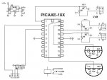
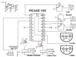
and almost done schematic, there might be errors:
 

Attachments

boelle

Member
figured that an XBee would be perfect to get 2 way coms, only question is if it would case trouble if both the XBee and the serial interface is used at the same time? ie connect both XBee and serial download circuit to pin 2 and 3. Of course i have to add divider network to ser out so that the XBee can handle it
 

boelle

Member
for the input to xbee i could just use a jumper, ie so that when i need to program the picaxe i do that by cable and the xbee is disconnected in the few secs it take... not abig problem as i do not plan to reprogram a lot when its working
 

graynomad

Senior Member
I still don't get why you can't use two seperate pins for the comms and leave the programming pins out of it.

You don't want to use the serin command because it blocks, is that right?

If so move to an X2 part with a timeout.
 

boelle

Member
Hi, i have used all the inputs for the sensors etc, is there was a input left i would have used that.

Remember i'm a noob so i might have overseen something
 

hippy

Ex-Staff (retired)
Note the 20M has less memory than an 18X; an 18M2 or 20X2 would be advisable. The usual approach is to draw a block diagram of what you want, fill in all the I/O signals to determine what you need, then fit the hardware to that.
 

Jeremy Leach

Senior Member
I'm new to this thread, but just stepping back and questioning why you need to have two way comms when the PICAXE could make the decision to switch on the heater itself ?

What is going to make you decide to activate the relay? Is it just when the temp drops below X degrees?

Or you could just use one way wireless to say that the PICAXE has turned it on.

I'm probably missing something here though.
 

boelle

Member
why i want to activate the relay is if i'm in the situation where i have not set the heaters own timer/clock to start, that could be if someone calls and i need to drive unplanned.

The heater can heat up the car in 30 mins or so, the same time i need for a shower and get some clothes on, so a switch on the base station is nice.

the transmitter will have 2 relays, one that controls the of the cabin fan is allowed to run, that one is controlled by the picaxe based on cabin temp

the other relay should just be controlled by a switch at the base station

have poked arround a lot and have yet not found a way to do it.. hmm... transmit a 0 or 1 value and use that to decide if the relay should be on or not... but how?
 

Jeremy Leach

Senior Member
Ok, I think I understand and I can see it's nice to have that control.

I suppose though, you don't strictly need to 'get' information back from the car? I mean, you could have one way comms to the car from the base station, to allow you to control the heater, and internal logic in the picaxe code to determine whether to actually act on the request, based on the actual temperature.

I see it would be nice to have 2-way comms though.
 

boelle

Member
hmm.. the idea was to get info from the car and the control would be a bonus...

am i heading for a dead end?
 

Jeremy Leach

Senior Member
No dead end at all - it's a very doable project with PICAXEs.

I was just challenging your need for bi-directional comms because it will all add to cost / complexity. Most projects seem to just monitor, so I was just checking :)
 

boelle

Member
i'm both a noob and stuborn at the same time..

but i have read some articles and figured that on the display i could use serout to transmit the value of the pin for the switch, it will be a high or low signal.

then on the transmitter in the car use serin to catch the value and store that in place as the output pin has its high low value stored... just a quick thought
 

Jeremy Leach

Senior Member
That sounds right. Have the PICAXE in the display unit monitor the status of the switches. As soon as you change a switch transmit the change to the Car Unit.

So perhaps have:
- The base unit polling the car unit at regular intervals (1 minute?) to get the temperature data and any other data.

- The car unit listens for the polling request. As soon as it gets a request it transmits the data back.

- If a switch changes on the base unit the regular cycle of polling is interrupted and a poll sent immediately (and in the poll signal send the status of the switches). Then return to regular polling cycle.


Or something like this.
 

boelle

Member
hi... that is at least what i have in mind, it got me much closer to the goal

next step is to look through my schemativ and order parts for a transmitter and build it on breadboard first, should be simple to test without the display unit as it will dublicate output to the programming cable, likewise for the display unit
 

boelle

Member
one last thing.... i read in the voltage by readadc, but I need it to be multiplied by 2.5, would this work:

ReadADC10 2, ADVal

TF_10 = ADVal * 2 ' 4.88 * ADVal
TF_10 = ADval * 5 / 10 + TF_10
TF_10 = ADval * 0 / 100 + TF_10

Whole_2 = TF_10 / 10 ' TF whole
Fract_2 = TF_10 % 10 ' TF tenths of a degree

Going to order parts today
 

hippy

Ex-Staff (retired)
I think the lack of comment is that no one's sure if your calculation is correct because they don't know your input values or what the output values should be for each input value, nor why you need to multiply by 2.5.

An indication of what the input values will be and what output values you desire would be useful.
 
Last edited:
Top