18m2 serout to 20x2 serin

sid

Senior Member
Hi all
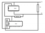
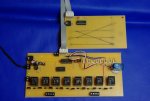
I've built two small circuits that are connected together with a ribbon cable that provided V+ and V- between both boards from the same on board power supply.
On the main board the axe is a 20x2, and on the secondary board the axe is an18m2 and they are connected together again via the ribbon cable from port C.7 on the 18m2 to port B.0 on the 20x2.
I want to get the 18m2 to talk to the 20x2 via the connection using serout and serin commands but for some reason although I can see the data leaving the 18m2 with a voltmeter, the 20x2 will not respond. I've checked and triple checked my wiring and connections which all seem to be ok.
The code I'm using is ......

on the 18m2 data out
Code:
ons:
high B.0
b2=1
serout C.7,n1200_8,(b2)
pause 10
serout C.7,n1200_8,(b2)
pause 10
goto main1
and on the 20x2 data in
Code:
start:
serin B.0,n1200_8,b2
if b2=1 then goto main
goto start
I've tried changing the baud rates and frequency but all to no avail.
Can anyone spot the obvious mistake ?????
And yes the input does have a 10k to earth
All suggestions gratefully received
 

hippy

Ex-Staff (retired)
The 18M2 runs at 4MHz by default so your baud rates should be N1200_4 ( or simply N1200 ).
 

hippy

Ex-Staff (retired)
Glad you got it resolved.

It can get a bit confusing when working with two different chips and moving between them. I find the best way to avoid confusion is to work to the standard of -

1) If there's no SETFREQ used within the program then specify baud rates without the frequency suffix, that is, use N1200 rather than N1200_4 or N1200_8

2) If there is a SETFREQ used, specify all baud rates with a suffix which matches the frequency used.
 

sid

Senior Member
I have another question.
I've attached a simple diagram of the two circuits. (leaving some parts off for clarity) the 18m2 sends a value to the 20x2 via a ribbon cable and then the 20x2 switch's a bank of relays via an 8bit shift register accordingly, however when the serin line of code is added to the 20x2 the relays go nuts constantly switching, take the code out and they don't do anything. I've tried adding a capacitor between the input on the 20x2 and ground and an additional 10k resistor but every time I add the serin line of code the same thing happens. It also happens when I use a readadc10 command instead of a serin command. I'm working on a table that is far removed from any electrical noise and I've run out of ideas. The only other thing I can tell you is that the relays stop going nuts when I touch any exposed part of the circuit, ie: the program socket, which I suppose would indicate a grounding problem ?
All advice welcome
 

Attachments

sid

Senior Member
From what you've indicated, you need to provide

the full circuit

the program

some hi-res photo's

e
Well I don't have the software needed to draw a proper diagram and the circuit/s are to big to draw in paint and I know you chaps get annoyed when people use pcb plans in place of circuit diagrams, however I do believe I've found the solution.
In the photo you can see two boards a mother and a daughter. The intention is to use the daughter board with an 18m2 as an input panel for a section of model rail track using the touch function as the input switch's. The idea being that one touches the panel indicating where you want the train to move from-to. These inputs are turned into a value which is sent to the mother board via a serout/serin command via the ribbon cable.
The 20x2 on the motherboard takes the input value and then sets the relays via an 8bit shift register and the servos directly from outputs accordingly.

Where I was going wrong was in the code on the receiving 20x2 which was
Code:
start:
serin B.0,n1200,b2
if b2=1 then goto two

one:
b1 = %11111111
for b0= 1 to 8
if b1 > 127 then high c.7 else low c.7
endif
pulsout c.4,10
b1 = b1 *2
next b0
pulsout c.5,10
goto start

two:
b1 = %01111110
for b0= 1 to 8
if b1 > 127 then high c.7 else low c.7
endif
pulsout c.4,10
b1 = b1 *2
next b0
pulsout c.5,10
pause 2000
b2=0
goto start
What was happening was that the relays where switching on/off rapidly for seemingly no reason, however what I think was happening was that the 8bit shift register was just scrolling 1's and 0's because it had not be given a command telling it what to do. By adding the following code at the start of the program the shift register stopped scrolling and set the relays and then waited for a command input from the daughter board.
Code:
prestart:
b1 = %11111111
for b0= 1 to 8
if b1 > 127 then high c.7 else low c.7
endif
pulsout c.4,10
b1 = b1 *2
next b0
pulsout c.5,10

start:
serin B.0,n1200,b2
if b2=1 then goto one
if b2=2 then goto two
if b2=3 then goto three
if b2=4 then goto four
if b2=5 then goto five
if b2=6 then goto six
if b2=7 then goto seven
if b2=8 then goto eight
goto start

one:
two:
etc
I left the circuit running for half an hour switching it on and off periodically and the problem seems to be solved. I've only ever used shift registers with leds before now and I suppose they would switch on/off with out me noticing, however a relay being switched on and off rapidly makes quite a racket. So I guess the moral of the story is set your shift registers at the start of your program. comments and advice welcome
 

Attachments

srnet

Senior Member
Well I don't have the software needed to draw a proper diagram
There are free to use ones out there, I use Eagle myself. You can use it just for circuit diagrams but it will do PCB designs (from the circuit diagram) too.

Be assured that doing proper circuit diagrams, and saving them, will save you many hours in the long term.

And its so mauch easier to ask others for assistance, if you have a decent circuit diagram.
 

sid

Senior Member
I've just ordered Livewire as it will compliment my pcb wizard software, plus it will show me how voltage etc flows a round a circuit, which for a novice like me might be quite useful.

I suppose in hindsight it might have been better to use two 20x2's, one to control the servos and one to control the relays directly doing away with the need for a shift register.
For some reason I always feel the need to do everything with one chip and I really should overcome this rather blinkered view. Still this is a prototype circuit so I guess I should expect a few learning curves along the way.
If anyone reading this thread is into model railways and is interested, the trackwork this circuit will be controlling can be viewed here http://www.rmweb.co.uk/community/index.php?/topic/37831-a-2mm-loco-service-point/ and then scroll down quite a bit.
 
Top