18M2 Programming Help Gratefully (urgently) Received!!!

DDJ2011

Member
Hi all,

Back after an absence of a few months. I'm still building my alarm clock which sprays water, but time is now critical so all help appreciated. The first competition is less than 2 weeks away - would be awesome if the Picaxe could take centre stage!

I have an AXE133Y display which (code below) can display my welcome message, plus it has the 18M2 that has a second timer for the clock part.

To make my code easier, I want to use the EEPROM command to set a message and then display that on the LCD.

Here is the code (an extract of the total code) that works for my welcome message. NB All of my code is derived from the Picaxe code or various forum posts:

Code:
	EEPROM $00, (" WHSG Engineers ") 	; store msg in the EEPROM memory
	EEPROM $10, ("2012 Alarm Clock") 	; store msg in the EEPROM memory
;
	gosub LCD_init
;
; display welcome message
	low rs					; command mode
	let b1 = 0				; message 0 on top line
	gosub msg				; do it
	low rs					; command mode
	let pinsB = 192		; move to line 2, instruction 192
	pulsout enable,1  	; pulse the enable pin to send data.
	high rs					; character mode again
	let b1 = 1				; message 1 on bottom line
	gosub msg				; do it
	end
;
LCD_init:
; power on LCD initialisation sub routine
	let dirsC = %11000111	; PortC 0,1,2,6,7 all outputs
	let dirsB = %11111111	; PortB all outputs
	pause 500		; Power stabilistation = 500ms
	let pinsB = %00111001	; Function set - select correct character table modes - ; 8 bit, 2 line, 5x8 , Western_European table1
	pulsout enable,1	; flush the instruction to the LED
	let pinsB = %00001100	; Display on, no cursor, no blink
	pulsout enable,1
	gosub Wipe
	return
;
Wipe:
; clear the LCD and prepare for text to display
	low rs					; command mode
; Display Clear
	let pinsB = %00000001
	pulsout enable,1
	pause 7			; Allow 6.2ms to clear display
; Return Home
	let pinsB = %00000010
	pulsout enable,1
; Entry Mode, ID=1, SH=0
	let pinsB = %00000110
	pulsout enable,1
	high rs			; Leave in character mode
	return
;
msg:
; EEPROM start address is 0 to 15 multiplied by 16
	let b2 = b1 & %00001111 * line_length
; end address is start address + (line_length - 1)
	let b3 = b2 + line_length - 1
; repeat 16 times (once per character)
	for b4 = b2 to b3			
		read b4,b1			; read next character from EEPROM data memory into b1
		let pinsB = b1 		; output the data
		pulsout enable,1  	; pulse the enable pin to send data.
	next b4				; next loop
	return
I would like some help with two problems:

First I want to overwrite an EEPROM value (say $00) with a new string that shows the time. For example
Code:
	EEPROM $00, ("Something") 	; store msg in the EEPROM memory
I get this error:

reprogram eeprom error.png

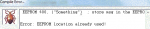
So problem 1 is how do I overwrite data using the EEPROM command (or any other command for that matter!)

Problem 2 is how do I concatenate a string to show the time that I can then write into the EEPROM data ($00) shown in problem 1? I'm pretty sure I can do the necessary maths to be able to extract HH MM and SS from the time variable.

Code:
EEPROM $01, (" " & <<some sort of command to build a string of values>> & ")"
Any help gratefully received.

DDJ
 

boriz

Senior Member
See: http://www.picaxe.com/BASIC-Commands/Variables/eeprom/

Specifically...

"The keywords DATA and EEPROM have identical functions and either can be used. This is not an instruction, but a method of pre-loading the microcontrollers data memory. The command does not affect program length. The EEPROM command only applies once at 'new program download'. When a program is being run the read and write commands are used instead to read and write the EEPROM data memory."
 

Goeytex

Senior Member
In simple terms EEPROM only loads data at program download time. To overwrite an EEPROM location or add a new value during program runtime, use the "Write" command.

Remember EEPROM has a limited number of write cycles and will eventually "wear out" .
 

hippy

Ex-Staff (retired)
Remember EEPROM has a limited number of write cycles and will eventually "wear out" .
As Goeytex says. Updating the EEPROM messages for the time display is the wrong way to go about doing what you want.

You want the time held in variables and to then split those variables into digits for display and directly send them ( and any other characters ) to the display.
 

DDJ2011

Member
Even more puzzled

Thanks for the comments so far - I understand now about what the EEPROM command is used for. I have been amending my code based on comments and also from searching across the forum and in the axe133 pdf.

I am using an axe133Y (built in 18M2) which I assembled myself.

This code (which only displays EEPROM messages) kind of works - I have commented in there where it stops working. Any ideas why this might be happening?

Code:
#picaxe 18M2
#define use_OLED
#TERMINAL 4800
symbol line_length = 16	; change to 20 for displays with 20 character lines
symbol enable 	= C.6	; LCD enable
symbol rs 		= C.7	; LCD RS 
; LCD data pins are on B.0 to B.7
	EEPROM $00, (" WHSG Engineers ")
	EEPROM $10, ("2012 Alarm Clock")
	EEPROM $20, ("  Manon, Ellie  ")
	EEPROM $30, ("  Yasmin, Nav   ")
	EEPROM $40, ("      End       ")

init:
	sertxd("At init")
	gosub LCD_init 		; initialise LCD
	sertxd("at welcome")
	gosub welcome			; display welcome message
'**********************************************************
'* Everything up to here works fine - the 4 welcome messages
'* display fine and the sertxd displays "at welcome"
'**********************************************************

main:
'**********************************************************
'* From this point onwards everything stops working
'* the sertxd displays gibberish (baud rate being re-set somehow?)
'* and the final EEPROM message ("      End       ") does not display at all 
'**********************************************************
	sertxd("main - wipe")
	gosub Wipe				; clear the screen
	sertxd ("about to pause")
	pause 3000
	sertxd("Pause over")
	let b1 = 5
	sertxd("main - wipe 2")
	gosub Wipe 				; clear the screen
	sertxd("go to msg =",b1)
	gosub msg
	pause 3000
	end
;
msg:
; display message from EEPROM
; message number 0-15 must be in b1 when called - uses (alters) b1, b2, b3, b4
; EEPROM start address is 0 to 15 multiplied by 16
	let b2 = b1 & %00001111 * line_length
; end address is start address + (line_length - 1)
	let b3 = b2 + line_length - 1
; repeat 16 times (once per character)
	for b4 = b2 to b3			
		read b4,b1			; read next character from EEPROM data memory into b1
		let pinsB = b1 		; output the data
		pulsout enable,1  	; pulse the enable pin to send data.
	next b4				; next loop
	return

welcome:
; display welcome message
	let b1 = 0				; message 0 on top line
	gosub msg				; do it
	low rs					; command mode
	let pinsB = 192		; move to line 2, instruction 192
	pulsout enable,1  	; pulse the enable pin to send data.
	high rs					; character mode again
	let b1 = 1				; message 1 on bottom line
	gosub msg				; do it
	pause 3000
	gosub Wipe 				; clear the screen
	let b1 = 2
	gosub msg
	low rs			; command mode
	let pinsB = 192		; move to line 2, instruction 192
	pulsout enable,1  	; pulse the enable pin to send data.
	high rs			; character mode again
	let b1 = 3
	gosub msg
	pause 3000
	setfreq m16
	return

LCD_init:
; power on LCD initialisation sub routine
	let dirsC = %11000111	; PortC 0,1,2,6,7 all outputs
	let dirsB = %11111111	; PortB all outputs
	pause 500					; Power stabilistation = 500ms
	let pinsB = %00111001	; Function set - select correct character table modes - ; 8 bit, 2 line, 5x8 , Western_European table1
	pulsout enable,1			; flush the instruction to the LED
; Display on, no cursor, no blink
	let pinsB = %00001100
	pulsout enable,1
	gosub Wipe
	return

Wipe:
; clear the LCD and prepare for text to display
	low rs					; command mode
; Display Clear
	let pinsB = %00000001
	pulsout enable,1
	pause 7			; Allow 6.2ms to clear display
; Return Home
	let pinsB = %00000010
	pulsout enable,1
; Entry Mode, ID=1, SH=0
	let pinsB = %00000110
	pulsout enable,1
	high rs			; Leave in character mode
	return
Looking at the axe133 pdf I should be able to do something as simple as this - but I get absolutely no output at all on the OLED:
Code:
init: pause 500 ; wait for display to initialise
main: serout B.7,N2400,(254,128) ; move to start of first line
serout B.7,N2400,(“Hello!123”) ; output text
end
So, I'm extremely puzzled. The OLED display looks great, but I can't get it to run as expected.

Any and all help gratefully received!
 

Technical

Technical Support
Staff member
At the end of welcome you setfreq m16. So now the chip, and sertxd, is running 4x faster than normal.
 

hippy

Ex-Staff (retired)
Looking at the axe133 pdf I should be able to do something as simple as this - but I get absolutely no output at all on the OLED:
Code:
init: pause 500 ; wait for display to initialise
main: serout B.7,N2400,(254,128) ; move to start of first line
serout B.7,N2400,(&#8220;Hello!123&#8221;) ; output text
end
Is that within the 18M2 on the AXE133Y board or from another PICAXE communicating with your 18M2 ?

I'm a bit confused as to what you are trying to achieve and how you are going about it.
 

DDJ2011

Member
Hi hippy,

Apologies for not being clearer. I have the axe133y with the attached 18M2.

I'm trying to program the 18M2 that is onboard the axe133y to display something on the OLED display. It will show EEPROM messages but not other text. Hopefully I don't have to program another (separate) chip to send messages into the axe133y-18M2?

Technical: so if I leave out the setfreq command my sertxd should work fine? I will try that tonight.
 

hippy

Ex-Staff (retired)
I'm trying to program the 18M2 that is onboard the axe133y to display something on the OLED display. It will show EEPROM messages but not other text.
What you need to do is use code which puts the data to the display and then tells the display it has got data, similar to how you have it in the copying EEPROM to the display routine ...

let pinsB = b1 ; output the data
pulsout enable,1 ; pulse the enable pin to send data.

In addition 'low rs' and 'high rs' determine whether the data is sent as a command to control the display (low) or data to be displayed on it (high).

You can create two routines which send a command and send data ...

SendCmd:
low rs
let pinsB = b1
pulsout enable,1
return

SendDat:
high rs
let pinsB = b1
pulsout enable,1
return

You can then write a sequence that clears the display ...

let b1 = %00000001
gosub SendCmd
Pause 1000

Puts the cursor at the home position ...

let b1 = %00000010
gosub SendCmd

And then displays something ...

b1 = "H" : gosub SendDat
b1 = "e" : gosub SendDat
b1 = "l" : gosub SendDat
b1 = "o" : gosub SendDat

To display time or anything else, just determine what each character will be, put it in 'b1' and call the 'ShowDat' routine.

Re SETFREQ; yes, if you remove all SETFREQ commands the 18M2 will operate at its default of 4MHz, SERTXD will always be at 4800 baud.
 

DDJ2011

Member
Hippy - Many thanks for your reply - I now have the display working as required.

I do have an additional question (of course!).

In the pdf for the axe133y it mentions Secondary Header H3 which provides connection points to the unused i/o pins (C.0, C.1, C.2) and power.

When I built my axe133y I did not solder in the appropriate pins for this header. However, I want to drive a pair of LEDs and a motor from the 18M2 on the axe133Y when the alarm is triggered and I suspect I need these pins available to do it.

How difficult would it be to solder in the H3 header now that the whole unit is built? Or, can I use the Main Header H2 which has a pin marked IN connects directly to the controlling PICAXE output pin to switch on (say) a Darlington pair to drive the LEDs and motor?

Apologies for the dumb questions but I'm really struggling with how to get this whole thing working.
 

boriz

Senior Member
I expect you can solder wires directly to the board if you don't want to use the header.

Borrowing from the firmware. To set the state of all three 'spare' outputs:
Code:
b1=%xyz      ; x=c.2 binary state, y=c.1 binary state, z=c.0 binary state
let pinsC = b1 & %00000111 | %10000000      ; output the data on C.0 to C.1, keep RS high
If you wish to address a single pin without effecting the state of the others, try this:

To force a pin HIGH:
Code:
let pinsC=pinsC or %xyz   ; where xyz is 0, that pin remains unchanged. where xyz is 1, that pin is forced HIGH
To force a pin LOW:
Code:
let pinsC=pinsC and %xyz   ; where xyz is 1, that pin remains unchanged. where xyz is 0, that pin is forced LOW
Two LEDs and a motor, all with simple on/off control yes? And no need for any inputs or buttons?
 

srnet

Senior Member
How difficult would it be to solder in the H3 header now that the whole unit is built?
Solder a pin header in place upside down, with what would normally be the top of the pins poking through the PCB. Easy to solder as you still have access to the top of the PCB.

Then remove the plastic strip that holds the pin header together (which would normally be flush with the PCB) with a sharp pair of cutters.
 

hippy

Ex-Staff (retired)
How difficult would it be to solder in the H3 header now that the whole unit is built? Or, can I use the Main Header H2 which has a pin marked IN connects directly to the controlling PICAXE output pin to switch on (say) a Darlington pair to drive the LEDs and motor?
The IN pin connects to PICAXE pin C.5 which is input only so can't be used as an output.

It should be easy enough to push wires into the H3 holes and apply solder from the top which will make the connections.
 

hippy

Ex-Staff (retired)
Solder a pin header in place upside down, with what would normally be the top of the pins poking through the PCB. Easy to solder as you still have access to the top of the PCB.

Then remove the plastic strip that holds the pin header together (which would normally be flush with the PCB) with a sharp pair of cutters.
Be careful doing that. I tried the same technique with veroboard/stripboard and the tracking quickly pulled away from the board. It might fare better with the PCB having plated through holes.
 

westaust55

Moderator
Then remove the plastic strip that holds the pin header together (which would normally be flush with the PCB) with a sharp pair of cutters.
The problem others on this forum have run into with this method is that cutting the plastic "carrier" forces the pins apart slighting during the cutting process which can tear the copper track.

Where I have had a need to solder a header onto the opposite side of a strip board or similar in the past I have mounted the longer sections through the board holes with the top of the pins flush with the non-solder board face and soldered keeping the solder with a low profile.
Then using broad nose pliers carefully press the plastic carrier down to the solder which gives enough pin length to achieve good contact and the plastic carrier still supports the pins so forces are distributed across all pins/solder/tracks.
 

DDJ2011

Member
Two LEDs and a motor, all with simple on/off control yes? And no need for any inputs or buttons?
That's the idea. My original plan was to build a working clock on board-1, with the axe133Y as display (board-2). Board-1 would also trigger the flashing lights and the water pump.

However, time is now short and in reality the clock will only be used once or twice at school electronics shows. So, the new plan is to build a "faux" alarm clock. Board-2 will now simulate a clock using the TIME function to update the display every second, and at regular intervals (say every 30 seconds) trigger the "alarms" (ie the LEDs and the pump).

Most of the time it will be switched off, when I switch it on, it'll display a couple of welcome messages then start the clock and alarm simulation - I'm hoping that will be enough to impress people.

That's the plan anyway! I have to say though that I'm really keen to build a fully working clock afterwards - it's the kind of module that could come in really useful in future.
 
Top