I have been driving an LCD display with an 18M via R330 resistors. No problem at 1st then the download started falling over after which the computer couldn't see the chip at all. Change chips, same story. The 08Ms, 14Ms have no problem with downloads only the 18Ms so it must be the chips. There is nothing on the board over 5.03v and I have reduced the voltage to the chip to 4.1v and fed the reset via a 4.5K resistor not a direct connection. Any ideas anyone?
18M dying
- Thread starter Maleny
- Start date
hippy
Ex-Staff (retired)
Unfortuantely comparing one chip with its circuit connection to another with different connections doesn't point conclusively to a problem with the 18M. If it's not simply the case that the 18M needs a hard-reset procedure to download code then it could be a circuit issue.
If you can post a full circuit diagram and your source code that may help. Also check for any shorts on the boards and between pins. There is no reason an 18M ( or any other PICAXE ) operated correctly should just die. We recommend trying a hard-reset first in case it is as simple as that.
If you can post a full circuit diagram and your source code that may help. Also check for any shorts on the boards and between pins. There is no reason an 18M ( or any other PICAXE ) operated correctly should just die. We recommend trying a hard-reset first in case it is as simple as that.
All I am doing at this stage is using the standard circuit, 22k in series with the serial in pin (#3 on an 18M) and a 10K to earth from the computer side of the 22k, then asking it to clear the memory. The thing is that a new 18M chip will work fine at first, the circuit and all the physical connections must be right it seems to me. I have tried hard resets and closing then reopening the editor but they don't want to play.
westaust55
Moderator
he does mention a reset resistor in post 1And the reset pin resistor....?
but left to assumption whether it is tied high or low. . . and fed the reset via a 4.5K resistor not a direct connection.
hippy
Ex-Staff (retired)
Testing an 18M with just a basic circuit ( power, download and reset ) might not work after and if the chip has been damaged from use in some other circuit.All I am doing at this stage is using the standard circuit, 22k in series with the serial in pin (#3 on an 18M) and a 10K to earth from the computer side of the 22k, then asking it to clear the memory. The thing is that a new 18M chip will work fine at first, the circuit and all the physical connections must be right it seems to me. I have tried hard resets and closing then reopening the editor but they don't want to play.
If the 18M's are working before insertion into the full circuit and for a while after that it does point to some issue with the circuit or using the 18M in that circuit.
If you are getting 18M failures with just the basic circuit, no other I/O connected, then that is something different which will have to be investigated further.
westaust55
Moderator
Never doubt the ingenuity of some folks - an seems the 18M is not doing much for much of the timeCan't imagine it doing much if tied low
westaust55
Moderator
True, unless there is one of the not so infrequent cases of a poor connection between a lead and a breadboard connection/hole.. and in permanent reset state it wouldn't be doing much for all of the time
Last edited:
David Lincoln (page 230) shows pin 4 tied high which is what I did 1st. Manual 1 (page 29) says it must be a 4.7K (not a 4.5k my mistake) so I tried that even though a assume this it's only for current limiting when the reset button is pressed. These chips don't just not work they go from working fine to failing verification to not being found on the com port (dying slowly). Even if they get as far as verification it seems to me the power and computer connections must be correct. I am using a brand new breadboard and have tried the chips in different positions. My conclusion is that I am damaging the chips somehow but there is nothing on the board more than 5.03v with the feed to the 18M now reduced to 4.1v, no inductive loads which need a catch diode and the LCD display is being driven via 330R resistors????????????? Could be the weather.
westaust55
Moderator
@Maleny,
some details about the power supply would also be warranted.
Is is a simple (unregulated) DC supply or well regulated.
If you are using a voltage regulator such as a 7805, do you have a 100nF ceramic cap and say a 22uF (or biigger) tantalum/electro cap in parallel on the output.
Some voltage regulator datasheets indicate that without the 100nF cap the voltage regulator can break into oscillation and then anything could happen at the output.
So please provide your full circuit diagram and a photo of the entire circuit for folks to review rather than just the information you think we need.
Oh dear, it would seem that we are down to belittling the good folk on this forum in the vain attempt at one-upmanship. A very "dippy" thing to be doing.Blimey, that's scraping the barrel....
Surely, all PICAXErs make sure their connections are good.... that's the first test for anyone with a brain.
http://education.yahoo.com/reference/thesaurus/entry/dippy
Please lets all try and keep this forum polite and above the average, without the sarcasm and poor humour.
Dippy. Though I can understand why some people confuse your uncompromising and forthright manner with rudeness, I’m personally honored to know you (In so far as I do). I guess it’s just one of the limitations of communicating by brief text only. More than half of the intended communication is lost. And although you do come across a little prickly sometimes, I’ve never seen any malice. And anyway, it don’t mean a thing if it ain’t got that swing. Vive la difference!
BeanieBots
Moderator
I think you'd make an excellent teacher Dippy.
You might get the sack because of some "do-gooder" parent's official complaint about their Johny being told things the way they are, but the rest would leave class with correct information and probably even remember it.
I had teachers that "put it blunt" and I'm glad I did.
You might get the sack because of some "do-gooder" parent's official complaint about their Johny being told things the way they are, but the rest would leave class with correct information and probably even remember it.
I had teachers that "put it blunt" and I'm glad I did.
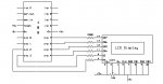
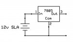
Having checked everything else I finally tried my last remaining 18M in my strip down test cct. Worked fine, replace it with any of the other chips and no go. Sure looks like damaged chips to me, but how is my question. Attached (I hope) are a ccts of the power supply and the one I was using when this problem started (manual 3, p38). Maybe the 330R resistors are not good enough to prevent static discharge with this display.
Attachments
-
 100.8 KB Views: 42
 -
 49.6 KB Views: 41
westaust55
Moderator
Would still recommend that you add the capacitors across the voltage reg output as mentioned back at post 14 plus another 100nF at/near the supply pins of the PICAXE.
The 330 ohm resistors between PICAXE and LCD are there just for current limiting is case you short a PICAXE output near the LCD end of the circuit. The circuit would still work if they are not there. Certainly not there for ESD protection.
The 330 ohm resistors between PICAXE and LCD are there just for current limiting is case you short a PICAXE output near the LCD end of the circuit. The circuit would still work if they are not there. Certainly not there for ESD protection.
BeanieBots
Moderator
A 7805 with 12v input DOES NOT make a 5v supply.
This is a common mistake and why it is mentioned so many times on here including in this thread.
Looks like you have killed the earlier devices you tried and I'd guess from your ealier confession that they were killed by poor/reversed power connections.
As pointed out by Westy, the 330R has absolutely nothing whatsovever to do with ESD. Your chip handling methods are the best way to control ESD.
Maleny, if you are going to use components (e.g. regulators) then get hold of the Manufacturer's DATA SHEET and give it a thorough read first.
Your example circuit and comments suggests that you haven't.
If , after READING the Data Sheet, you are unsure then post your circuit before trying it out. People will be glad to help or make suggestions.
If you rely on assumption and/or guesswork for your designs then you'll be popping a few more PICAXEs soon.
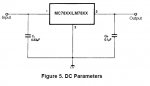
This is the minimum circuit from the datasheet. i normally use a 1uF on the input and a .1uF on the out put but anything is better than nothing. i made a rotating POV display with an 18X a while back and didnt include any caps, the picaxe would get to random stages of downloading before stopping. intalled the caps and it worked perfectly!!
Attachments
-
 36.5 KB Views: 13
westaust55
Moderator
@hobgoblin,This is the minimum circuit from the datasheet. i normally use a 1uF on the input and a .1uF on the out put but anything is better than nothing. i made a rotating POV display with an 18X a while back and didnt include any caps, the picaxe would get to random stages of downloading before stopping. intalled the caps and it worked perfectly!!
Are you addressing your opst to Maleny.
This thread as satrted by Maleny was pretty much concluded 5 months ago and Maleny is not a frequent poster so highly likely will not see your suggestion.