16X2 bit banging

Jakob2803

Senior Member
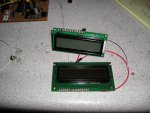
I recently received three 16X2 LCD displays I bought off of eBay. I would like to use them with the Picaxe and I was wondering if there was a guide for using it or bit banging it. (I will control it directly rather than use an AXE133). I have read several tutorials but they are all ATMega and use commands for LCDs rather than bit banging it. Help is apprecieted. :eek:
 

JimPerry

Senior Member
Need the type of display more precisely - most 16 x 2 are parallel and will work with an 18M2 and the AXE133 code no problem. :)

Bit banging is not really needed.
 

Jakob2803

Senior Member
See part 3 of the PICAXE manual.
I read it before posting and used the code example, I cannot get it to work. :(
I want to use method 3. The code in the manual is this:
Code:
EEPROM 0,(“Hellothere!”) ‘ store the text in the EEPROM memory
gosub init ‘ initialise LCD
main: let b1 = 1 ‘ set b1 to ‘clear display’ instruction
gosub wrins ‘ send instruction to LCD
for b3 = 0 to 4 ‘ setup for...next loop (“Hello” - positions 0 to 4)
read b3, b1 ‘ read letter from EEPROM into variable b1
gosub wrchr ‘ send character to LCD
next b3 ‘ next loop
let b1 = 192 ‘ set b1 to ‘start of second line’ position
gosub wrins ‘ send instruction to LCD
for b3 = 5 to 11 ‘ setup for...next loop (“there!”-positions 5 to 11)
read b3, b1 ‘ read letter from EEPROM memory into variable b1
gosub wrchr ‘ send character to LCD
next b3 ‘ next loop
The "init" subroutine is not in the program and so on and so forth. :) Where is the rest of the program?
 
Last edited:

SAborn

Senior Member
I cannot get it to work.
Then its likely a problem with your setup, have you wired it eactly the same as the manual shows in "option 3"

Have you checked the DB pins on the lcd with the correct data sheet, as not all 16x2 displays have the same pinouts. (many do but not all)

Have you swapped picaxe pins around if so the code wont work.
 

westaust55

Moderator
There is also the need to decide whether you are going to use a 4-bit or 8-bit parallel interface. Most folks use the 4-bit interfcae when going the parallel comms route to minimise the number of PICAXE IO required.
In the thread marks has linked to, 8-bit code is provided at post 1 and 4-bit code is provided at post 12.


Another option is the Rev Ed FRM010 serial to parallel LCD interface chip.
http://www.techsupplies.co.uk/epages/Store.sf/en_GB/?ObjectPath=/Shops/Store.TechSupplies/Products/FRM010
which reduces the pin count to 1 output pin and utilises the SEROUT command.
 

Kecked

Member
The picaxe evil genius book has a really nice section on LCD displays. I highly recommend it. There are also some nice tutorials in Nutz and Volts magazine.

Here is the Authors website. He posts the code if that is all you want. http://jrhackett.net/ I'd buy the book to support him.
 

Jakob2803

Senior Member
Does anyone have instructions for bit banging it? Like how it actually works. All these are just programs, and I can't even get them to work. :eek: I would rather learn how the 16X2 works and write my own code. :)
 

SAborn

Senior Member
If you are unable to follow the information in Manual 3, and get the display to work i doubt it can get any simpler.

You have a hardware problem somewhere and until you find and fix that no amount of bit banging will fix your problem.

Please draw us a schematic of your current setup, list the actual part number for the display, or the data sheet.
 

Jakob2803

Senior Member
If you are unable to follow the information in Manual 3, and get the display to work i doubt it can get any simpler.

You have a hardware problem somewhere and until you find and fix that no amount of bit banging will fix your problem.

Please draw us a schematic of your current setup, list the actual part number for the display, or the data sheet.
On the contrary I think the problem is with the program which is too advanced. There's a single gosub and several returns and other things, reading the code does not make sense to me at all. I just wanted to know how the 16X2 works, so I could try something simple... anything to see if it works.
I double checked the wiring when building it on the breadboard, but I will take a look at it later tonight. :)

Also those pulsouts, the notes say you are sending data. How are you sending data by pulsing the pin a single time? The code says pulse pin 3 for a hundreth (?) of a milisecond, how does that work to transmit data?
Code:
init: let pins = 0 ‘ Clear all output lines
let b4 = 0 ‘ Reset variable b3
let dirs = 252 ‘ Set pins 2-7 as output lines (Stamp only).
pause 200 ‘ Wait 200 ms for LCD to reset.
let pins = 48 ‘ Set to 8-bit operation.
pulsout 3,1 ‘ Send data by pulsing ‘enable’
pause 10 ‘ Wait 10 ms
pulsout 3,1 ‘ Send data again
let pins = 32 ‘ Set to 4-bit operation.
pulsout 3,1 ‘ Send data.
pulsout 3,1 ‘ Send data again.
let pins = 128 ‘ Set to two line operation
pulsout 3,1 ‘ Send data.
let b1 = 14 ‘ Screen on, cursor on instruction
[COLOR="#FF0000"]gosub wrins ‘ Write instruction to LCD[/COLOR]
[COLOR="#FF0000"]return[/COLOR]
wrchr: let pins = b1 & 240 ‘ Mask the high nibble of b1 into b2.
high 2 ‘ Make sure RS is high
pulsout 3,1 ‘ Pulse the enable pin to send data.
let b2 = b1 * 16 ‘ Put low nibble of b1 into b2.
let pins = b2 & 240 ‘ Mask the high nibble of b2
high 2 ‘ Make sure RS is high
pulsout 3,1 ‘ Pulse enable pin to send data.
[COLOR="#FF0000"]return[/COLOR]
wrins: let pins = b1 & 240 ‘ Mask the high nibble of b1 into b2.
pulsout 3,1 ‘ Pulse the enable pin to send data.
let b2 = b1 * 16 ‘ Put low nibble of b1 into b2.
let pins = b2 & 240 ‘ Mask the high nibble of b2
pulsout 3,1 ‘ Pulse enable pin to send data.
high 2 ‘ Back to character mode
[COLOR="#FF0000"]return[/COLOR]
 

Captain Haddock

Senior Member
Also those pulsouts, the notes say you are sending data. How are you sending data by pulsing the pin a single time? The code says pulse pin 3 for a hundreth (?) of a milisecond, how does that work to transmit data?
As I understand it the data pins are set to the relevent 1/0 values but the lcd module will not react to them until the pulse is sent to the enable pin, then the next 1/0 values can be selected on the data pins and enable pulsed again for the lcd to read them, read or command mode will depend on the state of the rs pin.
All the pulsout is doing is saying 'read this' to the lcd.
I have a feeling you could use the same data pins for 2 lcd modules as long as you use separate rs & e pins, anyone tried it?
 

Jakob2803

Senior Member
As I understand it the data pins are set to the relevent 1/0 values but the lcd module will not react to them until the pulse is sent to the enable pin, then the next 1/0 values can be selected on the data pins and enable pulsed again for the lcd to read them, read or command mode will depend on the state of the rs pin.
All the pulsout is doing is saying 'read this' to the lcd.
I see! :) Well this is the kind of info I need, how it works rather than how to program it. Can anyone expand on this? :) I wish they were as easy as shiftregisters :eek:
 

rossko57

Senior Member
Don't forget, that is only how one type of LCD can work. How yours might actually work is just conjecture, until you identify it/them.
 

westaust55

Moderator
To understand how to control the LCD you need to identify the controller chip (typically a Hitachi or clone thereof but check) and then read the data sheet.
The datasheets usually have a table with the commands and simple flow charts/sequences for how to initialize the controller chip.
There are some time intervals that must be considered when initializing and sending some commands (such as "clear the screen").

From your code snippet as posted, you are using a 4-bit data interface.
The code therefore must send each byte (the LCD controller works with bytes (8-bit wide) data and commands) as two 4-bit groups of data. Each 4-bit data (a nybble) requires a pulse on the data line to inform the LCD controller to load/accept the data.

EDIT:
here is a link to the Hitachi HD44780 controller datasheet if that is applciable to your (unknown to us) LCD's"
http://www.sparkfun.com/datasheets/LCD/HD44780.pdf
 
Last edited:

Jakob2803

Senior Member

JimPerry

Senior Member
You get what you pay for ...the ones you got are probably the same as sold by http://www.byvac.com/bv3/index.php?route=product/product&path=35_36&product_id=57 and are "upside down" to the one sold by Rev-Ed. :rolleyes:

I just purchased some chips' for another member in NZ, off Ebay - only 30 miles away and 20% cheaper - after 10 days still no sign oif them - could have got them next-day from RS/Farnell. :mad:

Hope you got a new soldering iron! ;)
 

Attachments

SAborn

Senior Member
Im still confused to what your problem is???

First your setup dont work or the code dont suit the setup, and you then you ask for raw information of how to drive the display and now cant read the data sheet Westy gave a link to, all you ever need to know is in the data sheet Westy listed.

Can you step back a moment and tell us a few things........ like are you using 4 bit or 8 bit mode with your setup.
What pins on which picaxe are connected to what pins on the display.
What do you see on the display when you try to use it (nothing, square blocks or something else)

They are a easy device to use if you set them up correctly and use the correct code in the right sequence, to be honest i would expect reading the data sheet might confuse you even more.
 

SAborn

Senior Member
If you can wire the display like shown in this schematic, with DB4-DB7 (4 bit mode) connected to picaxe pins all of one bank (A, B, or C) in numbered order from 0 - 3 (B.0, B.1, B.2, B,3 or C.0, C.1, C.2, C.3) and the En and Rs pins connected (they wont matter to which picaxe pins are used for them)

Then list what picaxe pins got to what display pins, i will then give you a test code example that should work, i just need to know what is wired to what pin.

Edit.... revised the schematic


View attachment LCD 28x2.pdf
 
Last edited:

Jakob2803

Senior Member
If you can wire the display like shown in this schematic, with DB4-DB7 (4 bit mode) connected to picaxe pins all of one bank (A, B, or C) in numbered order from 0 - 3 (B.0, B.1, B.2, B,3 or C.0, C.1, C.2, C.3) and the En and Rs pins connected (they wont matter to which picaxe pins are used for them)

Then list what picaxe pins got to what display pins, i will then give you a test code example that should work, i just need to know what is wired to what pin.

Edit.... revised the schematic


View attachment 12576
I am using the 20X2 if it matters. :eek: Backlight and contrast is sorted out. I do not have the resistors between the Picaxe and D-pins, does it matter?
B.0 is D4
B.1 is D5
B.2 is D6
B.3 is D7
C.0 is E
C.1 is RS

Edit: Oh and the other D pins are grounded. RE is grounded for now. Right decision?
 

hippy

Ex-Staff (retired)
I am using the 20X2 if it matters
It probably does. The code in the manual is for an LCD connected on a single port and would need to be changed if wired some other way -

B.7 to D7
B.6 to D6
B.5 to D5
B.4 to D4
B.3 to E
B.2 to RS

While code can be written to use any ports and any pins I would recommend sticking to the above ( or at least starting with it, and using one port ) so the code in the manual and other code which is compatible with it can be used for testing while developing your own code.
 

Jakob2803

Senior Member
It probably does. The code in the manual is for an LCD connected on a single port and would need to be changed if wired some other way -

B.7 to D7
B.6 to D6
B.5 to D5
B.4 to D4
B.3 to E
B.2 to RS

While code can be written to use any ports and any pins I would recommend sticking to the above ( or at least starting with it, and using one port ) so the code in the manual and other code which is compatible with it can be used for testing while developing your own code.
Sure! I used the C-pins because I figured it was easier to code, having them seperate from the Ds on B-pins.
 

SAborn

Senior Member
With it wired as you have listed in post #23 you can run this code and it should work, you will need to adjust the contrast to show characrers on the display.


EDIT:- the code below has been revised to match the code posted later in this thread, as there was a error in the code preventing the lcd to operate.
The code is now correct and works.

Code:
'&&&&&&&&&&&&&&&&&&&&&&&&&&&&&&&&&&&&&&&&&&&&&&&&&&&&&&&

'LCD Test program for 20x2

'&&&&&&&&&&&&&&&&&&&&&&&&&&&&&&&&&&&&&&&&&&&&&&&&&&&&&&&


'&&&&&&&&&&&&&&&&&&&&& Part 1 &&&&&&&&&&&&&&&&&&&&&&&&&&&&&&&&&&&&&


#picaxe 20x2

symbol temp =	        b0				'Temporary working variable for characters
symbol y =	        b1				'Variable used in "For/Next" loops
symbol en =	        C.0				'B.1 pin as display Enable
symbol rs =	        C.1				'B.0 pin as display reset 


setfreq m4	
	
	let dirsB = %00001111			'Set port A pins as outputs
	let dirsC = %00000011
	pause 200
	gosub init					'Initiate the display
	
	
'&&&&&&&&&&&&&&& Part 2 &&&&&&&&&&&&&&&&&&&&&&&&&&&&&&&&&&&&&&&&&&&&&&&&&


main:
	temp = 1					'clear the screen by sending a 1 
	gosub wrins					'write the instruction to the display
	
	temp = 128 					'select the top line of the display by sending 128
	gosub wrins					'write the instruction to the display
		
	for y = 0 to 14				'Loop to write each byte of the text below to the display (15 characters, 15 bytes)
	lookup y,("---- HELLO ----"),temp	'lookup each character and put in TEMP variable to be written to the display
	gosub wrchr					'Write each character to display
	next y
	
	temp = 197 					'start of second line
	gosub wrins					'write the instruction to the display
	
	for y = 0 to 10				'Loop to write each byte of the text below to the display (9 characters, 9 bytes)
	lookup y,("-IT WORKS-!"),temp		'lookup each character and put in TEMP variable to be written to the display
	gosub wrchr					'Write each character to display
	next y

	pause 1000
	
	goto main
	

'&&&&&&&&&&&&&& Part 3 &&&&&&&&&&&&&&&&&&&&&&&&&&&&&&&&&&&&&&&&&

	
init:
	low rs
	pinsB  = 0 :pulsout en,5		'reset all hardware
	pause 10
	pinsB = %00000010: pulsout en,5	'4 bit mode
	temp  = %00101100 : gosub wrins	

	temp  = %00001100 : gosub wrins	'display control

	temp  = %00000001 : gosub wrins	'clear display
	
	pause 2
	temp  = %00000110 : gosub wrins	'entry mode	
	
	return
	

wrchr:
	pinsB = temp/16
	high rs
	pulsout en,5
	low rs
	pinsB = temp and 15
	high rs
	pulsout en,5
	low rs
	return

wrins:

	low rs	
	pinsB = temp/16
	pulsout en,5
	pinsB = temp and 15
	pulsout en,5
	return


'&&&&&&&&&&&&&&& End &&&&&&&&&&&&&&&&&&&&&
 
Last edited:

SAborn

Senior Member
You asked about the need for the resistors (330R) i have in my schematic between picaxe and LCD, they are not exactly needed, but it is advised to include them if you are desiging a PCB to suit.

The LCD can induce EMF back to the picaxe, its not a common problem but can cause glitches, for the sake of $0.20 i find it easy to include them, also they can act as a jumper on a board allowing for tracks to be routed under the resistors, this comes in handy when desiging a board or working with bread board as its quicker to insert a resistor then to cut and strip some wire.

Its up to you if you include them or not, it should not prevent the display working if they are not used.
 

Jakob2803

Senior Member
I can't get the damn thing to work. :( I've checked the setup twice and I went through the very nice code you provided. I cannot find any errors in it. All the ports and pins match mine, and yet no response from the 16X2. I've checked the board I am using for the Picaxe and there are no broken connections anywhere. The unused D-pins as well as the RW are grounded through individual 470R resistors.

Edit: The lower line is solid so the problem is not the contrast, right? :eek:
 

SAborn

Senior Member
The lower line is solid so the problem is not the contrast, right?
I think the display is upside down, as its normally the top line with solid blocks, try dialing the contrast back till the blocks become faint.

It would appear that the display is not initalizing if all you get is blocls.
 

westaust55

Moderator
Concur with SAborn. The solid blocks in the character positions are usually in the top row - it has previously been mentioned in this thread that these display are upside down compared to normal orientation relative to the interface holes in the PCB.

The solid blocks are an indication that the LCD has not been initialised.
 

westaust55

Moderator
Try this untested modified version of the Init: subroutine to replace that provided by SAborn.
Based on 4-bit initialisation I have used in the past, but as stated - not tested

Code:
init:

	pause 500
	pinsB = %00000010: pulsout en,5	'4 bit mode
	temp  = %00110011 : gosub wrins
	temp  = %00110010 : gosub wrins
	temp  = %00101000 : gosub wrins	

	temp  = %00001100 : gosub wrins	'display control

	temp  = %00000001 : gosub wrins	'clear display
	
	pause 2
	temp  = %00000110 : gosub wrins	'entry mode	
	
	return
 

Jakob2803

Senior Member
Try this untested modified version of the Init: subroutine to replace that provided by SAborn.
Based on 4-bit initialisation I have used in the past, but as stated - not tested

Code:
init:

	pause 500
	pinsB = %00000010: pulsout en,5	'4 bit mode
	temp  = %00110011 : gosub wrins
	temp  = %00110010 : gosub wrins
	temp  = %00101000 : gosub wrins	

	temp  = %00001100 : gosub wrins	'display control

	temp  = %00000001 : gosub wrins	'clear display
	
	pause 2
	temp  = %00000110 : gosub wrins	'entry mode	
	
	return
It still does not initialize. It's very frustrating. :mad: The problem is obviously on my end but I cannot figure it out. Wiring is checked, and everything. :(
The pins are on the side of the solid line rather than the empty one. Is this a bad knock off display or does it have the proper layout? :)
 

SAborn

Senior Member
It makes no difference where the pins are some have them on the end of the display, and they all normally have the same pins but can be in different order, yours looks to be labelled on the board so it should be correct.

How have you attached to the LCD, header pins, wires, ??

I would double check your soldering on the LCD, also check you dont have a small solder bridge between pins on the LCD.

Its very rare to have a display that wont work and normally results in a construction fault somewhere.
 

Jakob2803

Senior Member
It makes no difference where the pins are some have them on the end of the display, and they all normally have the same pins but can be in different order, yours looks to be labelled on the board so it should be correct.

How have you attached to the LCD, header pins, wires, ??

I would double check your soldering on the LCD, also check you dont have a small solder bridge between pins on the LCD.

Its very rare to have a display that wont work and normally results in a construction fault somewhere.
I am using a pinheader. There are no solder bridges. :) All headers are soldered to their tab on the LCD. The pinheader is in a breadboard with jumper wires to the pinheaders on my Picaxe board.
 

inglewoodpete

Senior Member
I think you need to get serious. If you don't have a logic probe, get one or use an LED and a 330ohm resistor (I think a logic probe does the job better).

Put "Wait 5", "Wait 10" or "Wait 15" commands between each of the initialisation commands an see if you have the right value (0 or 1) on each pin of the LCD as the program progresses. It never fails to show up the problem for me when I have this sort of a challenge.
 

Jakob2803

Senior Member
I am checking with an LED. RS is always on. Enable lights the LED up faintly so it must be on only shortly. D4 is on pretty much all the time except for some short bursts of blinking. D5-7 blink in intermittent bursts.
 

SAborn

Senior Member
I had a thought about how you have the display wired to the picaxe with using both portB and portC, and i may have over looked this in the code, as i would normally use all one port.
I think Hippy touched on this some posts back.
The problem in the code was the reset pin is taken high and never returned low, as with using all one port this is automatically done with the "PinsB = xxxxxxxxx" lines of code
Also with the 20x2 the pins should be set as outputs before use, this was done for the portB but not for portC.
I have now added a " let dirsC = %00000011 " line to the preamble and also some " low rs" lines to code for the reset pin on the LCD.

Give this revised code a try using the same wiring as you had listed in post #23 (same as the last code i gave)


Code:
'&&&&&&&&&&&&&&&&&&&&&&&&&&&&&&&&&&&&&&&&&&&&&&&&&&&&&&&

'LCD Test program for 20x2

'&&&&&&&&&&&&&&&&&&&&&&&&&&&&&&&&&&&&&&&&&&&&&&&&&&&&&&&


'&&&&&&&&&&&&&&&&&&&&& Part 1 &&&&&&&&&&&&&&&&&&&&&&&&&&&&&&&&&&&&&


#picaxe 20x2

symbol temp =	 b0				'Temporary working variable for characters
symbol y =		 b1				'Variable used in "For/Next" loops
symbol en =		 C.0				'B.1 pin as display Enable
symbol rs =		 C.1				'B.0 pin as display reset 


setfreq m4	
	
	let dirsB = %00001111			'Set port A pins as outputs
	let dirsC = %00000011
	pause 200
	gosub init					'Initiate the display
	
	
'&&&&&&&&&&&&&&& Part 2 &&&&&&&&&&&&&&&&&&&&&&&&&&&&&&&&&&&&&&&&&&&&&&&&&


main:
	temp = 1					'clear the screen by sending a 1 
	gosub wrins					'write the instruction to the display
	
	temp = 128 					'select the top line of the display by sending 128
	gosub wrins					'write the instruction to the display
		
	for y = 0 to 14				'Loop to write each byte of the text below to the display (15 characters, 15 bytes)
	lookup y,("---- HELLO ----"),temp	'lookup each character and put in TEMP variable to be written to the display
	gosub wrchr					'Write each character to display
	next y
	
	temp = 197 					'start of second line
	gosub wrins					'write the instruction to the display
	
	for y = 0 to 10				'Loop to write each byte of the text below to the display (9 characters, 9 bytes)
	lookup y,("-IT WORKS-!"),temp		'lookup each character and put in TEMP variable to be written to the display
	gosub wrchr					'Write each character to display
	next y


	pause 1000

	
	goto main
	

'&&&&&&&&&&&&&& Part 3 &&&&&&&&&&&&&&&&&&&&&&&&&&&&&&&&&&&&&&&&&

	
init:
	low rs
	pinsB  = 0 :pulsout en,5		'reset all hardware
	pause 10
	pinsB = %00000010: pulsout en,5	'4 bit mode
	temp  = %00101100 : gosub wrins	

	temp  = %00001100 : gosub wrins	'display control

	temp  = %00000001 : gosub wrins	'clear display
	
	pause 2
	temp  = %00000110 : gosub wrins	'entry mode	
	
	return
	

wrchr:
	pinsB = temp/16
	high rs
	pulsout en,5
	low rs
	pinsB = temp and 15
	high rs
	pulsout en,5
	low rs
	return

wrins:

	low rs	
	pinsB = temp/16
	pulsout en,5
	pinsB = temp and 15
	pulsout en,5
	return


'&&&&&&&&&&&&&&& End &&&&&&&&&&&&&&&&&&&&&
#rem
B.0 is D4
B.1 is D5
B.2 is D6
B.3 is D7
C.0 is E
C.1 is RS
 

Jakob2803

Senior Member
It works! Thanks a lot SAborn. :cool: :cool:
By the way, what could I do to show a variable on the 16X2? Do I write the variable name in the lookup field?
 

SAborn

Senior Member
Cool, thats good news, its all too simple when it do work.

Im sorry for my mistake in the earlier code example and wasting your time, but you got there in the end.

Its a handy little test program to run to test the LCD before writing it into a main program, the reason it was set out in Part 1, Part 2, Part 3, was for someone else so to explain you can just copy paste Part 3 into any program and also Part 1 too, with a few slight changes to suit your pinouts used.
Then Part 2, is just your normal program where you call the gosub for wrchr (write character) or wrins (write instruction)

Have fun!
 
Top