1 x 16 LCD have a go

Basrad

Member
Hi, Hope all are well?

I'm having a go with the LCD module as explained in pdf 3.

Iv gone with method 3, direct connect to PIC as i have 16 pins on it.

On the diagram, im a bit confused as to which Pins of the Picaxe to connect it up to?

E.G DB6 is pin 12 on my LCD unit, and on the pdf is says pin 5... (is that pin 5 of the pic?)
 
Last edited:

Basrad

Member
The Code is as in the PDF..

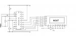
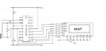
I Cant see which bit relates to the output pins of the PICAXE :( 18M

EEPROM 0,("Hellothere!") ' store the text Hellothere! in EEPROM memory

gosub init ' initialise LCD command

Main: let b1 = 1 ' sets b1 to 'clear display' instruction
gosub wrins ' send instruction to LCD

for b3 = 0 to 4 ' setup for...next loop ("Hello" - positions 0 to 4)
read b3, b1 ' read letters from EEPROM into variable b1
gosub wrchr ' send charater to LCD
next b3 ' next loop

let b1 = 192 ' set b1 to 'start of second line'
gosub wrins ' sent instruction to lcd

for b3 = 5 to 11 ' setup for next loop ("there!" - positions 5 to 11)
read b3, b1 ' read letters from EEPROM memory into Vary b1
gosub wrchr ' send charaters to LCD
next b3 ' next loop

init: let pins = 0 ' Clear all output lines
let b4 = 0 ' Reset variable b3
let pins = 252 ' Set pins 2-7 as output lines (Stamp only).
pause 200 ' Wait 200 ms for LCD to reset.
let pins = 48 ' Set to 8-bit operation.
pulsout 3,1 ' Send data by pulsing ‘enable’
pause 10 ' Wait 10 ms
pulsout 3,1 ' Send data again
let pins = 32 ' Set to 4-bit operation.
pulsout 3,1 ' Send data.
pulsout 3,1 ' Send data again.
let pins = 128 ' Set to two line operation
pulsout 3,1 ' Send data.
let b1 = 14 ' Screen on, cursor on instruction
gosub wrins ' Write instruction to LCD


wrchr:let pins = b1 & 240 ' Mask the high nibble of b1 into b2.
high 2 ' Make sure RS is high
pulsout 3,1 ' Pulse the enable pin to send data.
let b2 = b1 * 16 ' Put low nibble of b1 into b2.
let pins = b2 & 240 ' Mask the high nibble of b2
high 2 ' Make sure RS is high
pulsout 3,1 ' Pulse enable pin to send data.
return

wrins:let pins = b1 & 240 ' Mask the high nibble of b1 into b2.
pulsout 3,1 ' Pulse the enable pin to send data.
let b2 = b1 * 16 ' Put low nibble of b1 into b2.
let pins = b2 & 240 ' Mask the high nibble of b2
pulsout 3,1 ' Pulse enable pin to send data.
high 2 ' Back to character mode
return
 

Basrad

Member
On my 18M these numbers do not meet up with my output pins...

Does this mean the 18M cannot be used for the matrix LCD? Can I only use the 18M2 which can have these pins turned into outputs?
 

hippy

Ex-Staff (retired)
The 18M has 8 outputs so can drive the LCD as described; don't confuse pin numbers with leg numbers. If that's not the case then you'll need to explain how you mean.
 

Basrad

Member
So where it says in the program example

let dirs = 252 ' Set pins 2-7 as output lines (Stamp only).

<just noticed i typed pins on this line!!>


means Set the Pins of the chip / Or output pins...?

You say Pin numbers and Leg numbers... This does confuse me..which is which? and what does Stamp Only mean?

Thank you for your guidance so far :)
 

hippy

Ex-Staff (retired)
The "(Stamp only)" means that line is only required for the Stamp, not the PICAXE, can be left out for PICAXE use.

Not entirely true as some PICAXE default all their "input and output" lines to input and do need a "let dir" type command.

As to the difference between legs and pins; legs are the favoured term for the physical legs of the chips, pins are what are controlled and used by software commands which are allocated to specific legs, as show in the pinout diagrams in PICAXE Manual 1.
 

Dippy

Moderator
Uh oh , the leg / pin confusion rises again...

Remember, on the BASIC stamp all the data pins (or 'legs' as about 5 people call them) are Input or Output types.
So, you need a Direction command (DIRection) to set them as Input or Output.

Some PICAXEs have the data pins pre-set as Input or Output.
Some are configurable and may require a DIR command just like the Stamp.

Sadly, we're back to this "pin" / "leg" confusion.
Some people go on about "physical Leg 10" for example.
When you refer to the Pinout diagram (not "legout diagram" you'll note) you will see this is simply called "Output4" or "Out4".
If people kept to that convention then, in most cases , we could avoid this entirely non-standard "Physical Leg 10" stuff.

So, use the Pinout digrams and look at the actual Indentity used to describe the pin, sorry hippy, I mean "leg" :)
E.g. 18M. If you connect to the I.C. pin 10 ("physical leg 10"), you should refer to it as "Output4" or "Out4" on your schematic.

May I suggest you post a schematic circuit diagram showing EXACTLY how you have connected the things together.
Then we can avoid the textual confusion and get down to brass tacks .. or is that pins ... or legs...?
 

Basrad

Member
OK..

So a Stamp is the PIC without the PICAXE pre -config header software installed..

I am using a 18M (16F819)

Leg, refers to the total number of 'legs' on the Chip

Where as Pin is refering to either the Output or the Input Pin set... Will these be Pin 0 - 7

I have followed the LCD Diagram in the PDF3... I have tryed 2 configs (Pins and Legs :(

This is the current setup....
 

Attachments

BeanieBots

Moderator
"Stamp" is a (much more expensive) competitor to PICAXE.
The languages are very similar so code can often be ported between them with little modification.

A PIC without the bootloader is .. well .. um .. a PIC.
 

Svejk

Senior Member
I may miss something but:

in Picaxe Manual #3, p. 38 the pin numbering is:

7 - DB0
8 - DB1
9 - DB2
10 - DB3
11 - DB7
12 - DB6
13 - DB5
14 - DB4


And I believe that's not correct. If the setup follows the LCD pins then it won't work. The correct way should be 8..14 to correspond to DB0..DB7.
 
Last edited:

hippy

Ex-Staff (retired)
There is a discrepency on pages 35 and 38 between LCD pin numbers and their naming. The following are correct for the examples in the manual -

PICAXE Output Pin 7 -> LCD pin 14 = "DB7"
PICAXE Output Pin 6 -> LCD pin 13 = "DB6"
PICAXE Output Pin 5 -> LCD pin 12 = "DB5"
PICAXE Output Pin 4 -> LCD pin 11 = "DB4"
 

Basrad

Member
Thanks! How do you know whats correct and whats not? I cant see / understand which line or command refers to which pins will be used at all?
 
Last edited:

hippy

Ex-Staff (retired)
Thanks! How do you know whats correct and whats not?
In the general philosophical case by reference to additional material; don't automatically believe what you see on the news, read in the papers, find on a website or read in documentation, keep your mind open to the possibilities that it may not always be 100% correct.

I cant see / understand which line or command refers to which pins will be used at all?
That comes through experience and gaining knowledge; knowing how the hardware connects, what is required to control that hardware and the code which implements that control. This will sometimes be aided by source code comments and additional documentation which describes what the code is doing and sometimes why.
 

westaust55

Moderator
Your diagram is correct with respect to the PICAXE to LCD module but there is a problem with the LCD terminal identification (due to an error in PICAXE Manual 3).

See the attached (the 4 terminals encircled in red box)

Ah okay I see there is a page 2 to the thread now and this topic is already covered
 

Attachments

hippy

Ex-Staff (retired)
The draft of Manual 3 has been updated and will be published in due course. LCD connections are as per the attachment -
 

Attachments

Basrad

Member
Still cant get it to work.... Blank screen, nothing at all... hufff... Oh well... As they say, If at first you dont succeed try try and try again
 

hippy

Ex-Staff (retired)
Have you tried adjusting the contrast ?
What happens when you only connect LCD +V, 0V and contrast ?
Does the LCD require a negative voltage for the contrast ?
Is it a 5V LCD, or now a dead 3V3 LCD ?
Is it a wiring error ?
Is it an LCD pin number counting error ?
Has the power voltage ever been reversed ?
Has the LCD ever worked ?
Was the LCD bought new, and from where, eBay ?

All these issues are part of the reasons we recommend the AXE033 or FM010. Parallel control of LCD can often be false economy. Saving costs in one place can often translate into costs elsewhere, such as spending your own time and others in getting things to work.
 

Basrad

Member
You're right hippy, maybe parallel isnt the way to go.... But i'm using what i have to hand..

I have a number of diffrent 'unbranded' screens that I was given. They are all 1 x 16 though.

They all have 16pins, and pin 1 is clearly labeled on them. I would guess they are 5volts...

There was a generic data sheet with them, that seems to lead me to believe they are 5 volt units.. (I hope they are... The back light comes on at 4.5Volts :eek:S

You could be onto a winner with the contrast suggestion, Ill try that tomorrow.. As for the rest, I'll have to strike them off 1 at a time...

As for ebay, I was reading that you can get some really high quality stuff cheap there! ;)

The only bad thing I ever got was a Micro SD card.. 8 Gig, got to 4Gig and was randomly full!! You gotta give the buggers A for effort tho!

I buy solar cells on there, and theyr real good :)
 

Svejk

Senior Member
@Basrad: I'm drawing your attention that not for all LCDs the pinout layout is the same. It pays to read the datasheet for it. Also a good resolution photo may help if you wish to post one.
 

BeanieBots

Moderator
Have a look at the back of module to get the chip numbers.
Then use Google to find the datasheet(s).

You might need to have a negative supply for the contrast control.
You might need totally different codes from the ones you are using to initialise it.
You may well have already broken it.
 

Dippy

Moderator
NEVER assume a pinout - heed Svejk's advice.
And as BB says, you may have broken them, or maybe they were given to you because they were duff?


At this stage you have 3 variables:-
1. Is your code good?
2. Is your wiring correct?
3. Do the LCDs work?

Whilst I hate spending other people's money I would always advise the novice to buy good stuff from a good source with a bleedin precise data sheet.:)
Once you have got over the hurdle of getting something to work then you can experiment with unknown devices.
Buying a good LCD removes Variable(3) from the it-don't-work equation.

I hope it works out.:)
 

hippy

Ex-Staff (retired)
Good question; is the program code correct ?

In this case, no, the program drops out of the main program into 'init:', would normally hit a RETURN and then it's off somewhere into The Twilight Zone. Even worse, "init:" drops into "wrchr:", there's a missing RETURN there.

So that amounts to being on a hiding to nowhere from the off.
 

Basrad

Member
Ok, So There is a code problem... Will Look into that,

I have found the Data sheet for one of these units, Its a Data Vision 16100

I have attached the data sheet, and from what i understand of it, It should be compatible with a working software code?
 

Attachments

Dippy

Moderator
Superficially it looks like it. Hopefully your LCDs are fully functional.

Anyway, sort the code first.
Make sure your Power supply and contrast connections are correct, lots of people mess this up (esp with GLCDs).
 

Basrad

Member
Ok, wired up as directed, Changed code, as i think directed, Now all 8 right hand blocks are black and nothing else happens.. I will try a fresh LCD... Glad I'm just playing and dont urgently need a screen for anything, or I'd be venting steam by now :eek:S

Thanks for all your input so far all, Glad we found the odd error here and there so far
 

Dippy

Moderator
Yes, it can be frustrating.

If it were me and I needed it urgently I'd have bought a branded make of LCD rather than relying on 'unbranded' devices of unknown functionality.

Do you have ANY means (e.g. a firmware chip) to actually PROVE that those LCDs work?

You'll get there sooner or later, but as a lesson learnt, if you base something on unknown devices you really can waste oodles of everyone's time.
 

John West

Senior Member
I see in your data sheet that the controller used is a KS0066U. I don't know offhand what controller command set is used in the PICAXE docs, but it may well be different than what the KS0066U requires.

There are various different control chips used for various different LCD modules, often not command compatible. If that's the case, your control code will have to be derived from your data sheet, not from the PICAXE manual.
 
Last edited:

Basrad

Member
Ok, I'm going to buy a spanking brand new LCD.. Can any one recomend the cheapest / simplest / compatible options?
 

hippy

Ex-Staff (retired)
Ok, I'm going to buy a spanking brand new LCD.. Can any one recomend the cheapest / simplest / compatible options?
I'd suggest the AXE033 plus a set of 0.1" header sockets so you can swap LCD around rather than just buying the LCD display part. Buy 0.1" pins and headers for use with the other LCD you have.

That way you'll have a 'works out the box' display and then you can drop in other LCD to check they also work. You also have the AXE033 display which you know works and can be connected directly to a PICAXE to get a parallel interface working. The caveat is that you have to accept all risk in doing these things.

It's always best to have something which works then you can test by substitution. With two or more unknown quantities you don't know what works and what doesn't.

www.techsupplies.co.uk/AXE033
 

Dippy

Moderator
Wise words. My philosophy exactly. I've probably said it hundred times before on this Forum.
When something is new or you are inexperienced then MINIMISE the variables.

Once you start turning into a Big Boy you can start pushing it a bit as you will have a Book of Skills you can use, and of course your Grimoire of circuits and code.


Blimey, I used like Molesworth. I had the Compleet Molesworth until I gave it away recently. Cave! Cave! Oh these Comp boys don't know what they have missed. :)
 

John West

Senior Member
My philosophy has always been to work in low light, with incorrect documentation, using unmarked, underrated, unidentifiable components, poorly soldered, in questionable configurations, connected by a rats-nest of identically colored wires, driven by underpowered and noisy power supplies, in an unsafe work environment, while troubleshooting with erratically unreliable and inappropriate test equipment that I'm not too sure how to operate, in a hurried time-frame with a supervisor looking over my shoulder and asking stupid questions while making veiled threats about me 'losing my job over this' - in order to do everything wrong that can possibly be done.

Thereby learning all there is to know about what NOT to do and how not to do it, ensuring that I will at some point in the future finally understand how to do everything correctly.

Not sure how far along I am in my quest, but I am slowly making rapid progress.
 
Last edited:
Top