08m Base module

SgtB

Member
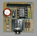
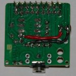
I wanted a 08m in a base style sort of like the arduino's and their shield system. I use the 08M in so many small temporary projects that I got tired of prototyping the basic picaxe core. All 8 pins are brought up through the female header sockets. All the pins are on 0.1" spacing so generic protoboards stack right on it. The power can be brought down from the add-on board or provided by a battery pack. The serout pin is switched. This is my first successful toner transfer board so I'm a little excited about that. I used toner for the silk screen too.(Click for a bigger pic)
 

SgtB

Member
Thanks. The old laser printer and iron process is what I meant. I've been protoboarding forever and finally just got around to etching my own boards. It's suprisingly quick and easy. If you need any tips let me know.
 

Andrew Cowan

Senior Member
Thanks. The old laser printer and iron process is what I meant. I've been protoboarding forever and finally just got around to etching my own boards. It's suprisingly quick and easy. If you need any tips let me know.
Were you printing onto photo paper, or the special PCB toner stuff (usually blue)?

A
 

SgtB

Member
I've got a free subscription of car&driver magazine through work. It's really glossy, and super cheap paper. Transfers good, and practically melts under water. It's smear resistant too. I just line the board up to the paper and use the iron's tip to stick one corner, and then lay the iron on the board for about 5 minutes. I then just slide the iron's tip across the paper until I can see the design through it a little. I usually set it in the fridge with tongs to set it quicker before I wet it.

Were you printing onto photo paper, or the special PCB toner stuff (usually blue)?

A
 

Minifig666

Senior Member
What temprature setting do you use on your iron I have been trying the toner transfer metod but I can't get it to work?
 

SgtB

Member
Eleventy billion, or as high as it goes.:D I usually set the iron on the board and pre-heat it for a few minutes. I use 0000 steel wool and soap to get it really clean first. I've switched to kinkos glossy magazine paper.

The toner and the paper are the two most important items. You want good toner transfer and paper that melts away under water. Photo paper that has plastic in it is useless. I haven't found a good one, and everything you read online is outdated on what paper to use.

I'm now using a laminater for the transfer. It is waaaaaaaaaaaaay better and worth every dollar. I run mine through twice. I use clear shelving "paper" for double sided boards. It's a very thin, cheap, clear self adhesive plastic. Just stick it to the other side of the board and laminate it. etch, peel it off and the reverse everything and etch again. I've gotten to almost 100% success rate. It's very fast too once you get a routine.

I might make a video.

braindump:
end
 

westaust55

Moderator
PICAXE 08M base module

SgtB,
well done on building your own. there can be great pleasure in "doing your own thing".

My solution for the same purpose was to buy an AXE021 kit and cut off the small proto area so that I was left with a small board with the PICAXE08M, program socket and resistors, capacitors and headers pin & socket strip to enable plugging into a bread board etc

http://www.rev-ed.co.uk/docs/axe021.pdf
 

Attachments

Last edited:

BeckettM

New Member
SgtB ....nice work and will be very handy in the future.

Mine was along the lines of Westaust55, but has some other advantages.

Some time ago I took some 11 yr olds for a picaxe introduction, and to overcome the possibility of wires coming loose, we decided to use the Axe021 board, which along with a 270 point breadboard, we double-side taped to the battery box, .

We fitted 330 ohm resistors to each input/output and a pullup to Pin3.
We fitted a single strand wire (inc the power), which could then be shifted around the breadboard as required.

Mine (photo) is not stuck together, but it made a very compact and easy to use piece of hardware, which still serves my son 6 years later.

I still believe using the 3.5mm download cable is better than the 3 pin arrangement, for begineers.
For my daughters one, the only change I intend is to put something under the breadboard, as the double sided tape can pull the breadboard apart if it gets rough treatment.

Cheers
Mark
 

Attachments

Last edited:

hippy

Ex-Staff (retired)
I still believe using the 3.5mm download cable is better than the 3 pin arrangement, for begineers.
I was a great fan of the 3-pin molex and reluctant to adopt to the jack socket, but have now gone over to the 'dark side' :)

The 3-pin molex has a smaller footprint and can be placed almost anywhere on a board while being easier to fit and solder. I still consider the 3-pin molex to have advantages over the jack socket but the real problem comes with the 3-pin socket and cable assembly. There's nothing intrinsically flawed about it but it doesn't stand the test of time so well with multiple connections and disconnections, plus being stepped on or rolled over by chair castors ! There is nothing more annoying and frustrating than a PICAXE appearing not to work and eventually finding a dodgy connection between pins and socket.

With Rev-Ed having moved to the jack connection scheme, particularly with the USB AXE027 cable and project boards fitted with jack sockets, it doesn't make much sense to use 3-pin molex in most cases these days. The 3-pin molex and jack sockets are the same price, the 9-way D to jack cable is 40% cheaper than the 9-way D to molex cable.

It's usually easy enough to add a 3-pin molex to a board that has a jack socket, which is what I used to do, but that is somewhat 'wasted effort'.
 

BeanieBots

Moderator
I was a great fan of the 3-pin molex and reluctant to adopt to the jack socket, but have now gone over to the 'dark side' :)
I've not gone over to the dark side but I do understand why it exists.
The jack socket does suit the target audiance better and many of the project boards together with the USB download cable leave you with no choice.
Being an RC'er, I have many Futaba style three pin plugs/sockets which I use. A quick and easy board connection can be realised with just a row of 3 SIL pins. To this end, I simply use an adapter cable (jack to 'Futaba') and enjoy the best of both worlds.

P.S.
My ('standard') 3 pin pinout is different to the Molex pinout so be careful with any designs I've published here.
 

SgtB

Member
Thanks for the compliments. I like the protoboards a lot. I wish I would have made my board like yours. I was really just having fun with diptrace and the etching and didn't think long enough on my pin layout. It's a real pain to route add on boards for this thing! I ended up building another breakout that stacks on top of it with most of the sensor and output options I want. My next one will have a single row of pins.

I use both molex and jack connections. Honestly, it just depends on what I have in my parts bin. I'm out of jacks, but it's going to take a while to burn through 4k pins. ;) I usually use jacks on my more mobile stuff. My bot has one because it stays tethered to the laptop way too much. :eek: I have a set of adapters too. My 3 pin molex is on a nice spiral wound cord so it gives a little more.
 

BeckettM

New Member
Over the last few days I have been playing with an 08M driving an LCD, all on a breadboard.
I was stuck with either pulling the 08M and programming and inserting, etc, etc, etc.

To overcome it I used an axe021 board with the chip removed, and ran three wires from the ic socket (leg 2, 7, 8) to the breadboard....thus saving sanity, while retaining the 3.5mm connection for my cords, and eliminating the need to add a resistor to hold down leg 2.

So another possible solution...but I can understand to need to use what is readily available.

Mark
 

SgtB

Member
That's one of the first things I built. Mine has In, Out, and reset with a switch. It really helps with prototyping.
 

BeckettM

New Member
Would this be better?

A couple of quid next time you order.
Saves a lot of hairy wires that might fall out :)
Dippy
Good idea and yes it could be a good alternative to hairy wires. (using strands of cat 5 cable eliminates the hairy bit, and gives some colour coding)

Unfortunately I haven't seen them here in NZ, however I do think there are some similar products.

It was interesting that I could have solved some of my changes by running the simulator, and proving my hacked software...it actually told me there were too many nested gosubs.:rolleyes:

Cheers
Mark
 
Top