Tilt switch test rig
- Thread starter Rampz
- Start date
David_Reynolds
Well-known member
I see, but if you are current limiting the input pin Via a resistance so when it parts company with the switch contact all that happens is the bounce is smoothed out, no more current flows and the CPU pin stands stead at zero or 5V , assuming you are using pullup or pulldowns whichever way you are initiating the input.
I do know a little about welding caps, but trust me with five volts and the fact you are not charging up an open ended cap I see no problem .
Smoothing across an open contact is of course a little different and requires a resistor in series with the cap, gauged to snub only within the current limit of the switch, this is not a problem if you want to ignore the subsequent pulses in the program.
Dave.
Last edited:
Rampz
Well-known member
Dave, yep all my reference is to what was happening previously, it was a max ox 14v through a tilt switch onto the gate of a mosfet the capacitor and resistor network across the tilt switch was 47 ohm and 22uf from memory and it wasn't going well for the tilt switch, as well as contact bounce they were trying to extend the pulse.I see, but if you are current limiting the input pin Via a resistance so when it parts company with the switch contact all that happens is the bounce is smoothed out, no more current flows and the CPU pin stands stead at zero or 5V , assuming you are using pullup or pulldowns whichever way you are initiating the input.
I do know a little about welding caps, but trust me with five volts and the fact you are not charging up an open ended cap I see no problem .
Smoothing across an open contact is of course a little different and requires a resistor in series with the cap, gauged to snub only within the current limit of the switch, this is not a problem if you want to ignore the subsequent pulses in the program.
This is not your
2 areas of interest now, looking at making an interface for old models of controller that will allow me to alter the state of the tilt switch and still get the same action and the second being going picaxe based for the whole control system, but along the way with both trying to find out just what the intermitant issue is with them, the main issue with the previous issue with the 555 setup is occasionally the 555 doesn't seem to being triggered at all long enough for the clock to stop, a picaxe interface will be able to display the state of the switch at all times for fault finding, this was the whole basis of the test rig to try and find answers as to why it stops
PhilHornby
Senior Member
Is there any intention to use the tilt switch to determine that the mechanism is sufficiently tensioned? ... or just that it needs tensioning?
The latter will occur very slowly - and may be indeterminate 'for quite a while' (30 secs?) - depending on the sensor.
Even if not used to determine sufficient tension has occurred, I can imagine the sudden removal of motor power from creating a false tilt (dependent on exactly what is inside said tilt switch). I don't think you've reported any instance of that though.
So I'm thinking - do HUGE de-bounce in software - i.e. has the tilt switch STAYED tilted for (say) 30 seconds. If not, restart the 'debounce'. (So not just a
(I'm thinking the use of a slowly ramping PWM to drive the motor would be advantageous too (to get rid of the 'jolts').
The latter will occur very slowly - and may be indeterminate 'for quite a while' (30 secs?) - depending on the sensor.
Even if not used to determine sufficient tension has occurred, I can imagine the sudden removal of motor power from creating a false tilt (dependent on exactly what is inside said tilt switch). I don't think you've reported any instance of that though.
So I'm thinking - do HUGE de-bounce in software - i.e. has the tilt switch STAYED tilted for (say) 30 seconds. If not, restart the 'debounce'. (So not just a
pause).(I'm thinking the use of a slowly ramping PWM to drive the motor would be advantageous too (to get rid of the 'jolts').
Rich (BB code):
do
      TIME = 0                            ;reset timer
      tiltDetected = 1                    ;say tilted

      do while TIME < 30                  ;examine pin for 30 seconds
            if TiltPin <> tilted then     ;not tilted
                  tiltDetected = 0        ;say not tilted
                  exit                    ;abandon check
            endif
      loop

      if tiltDetected then
            ;ramp-up motor for required time
            ;ramp-down motor for required time
      endif
loop
Rampz
Well-known member
Thanks Phil, only need to detect when it needs tensioning, and your right the may well be 30 seconds or longer when the tilt switch can't mak its mind up, from the test clocks i have worked on while testing it has often taken 15mins between drive pulses, you can't see the drum rotating, i don't think the current test rig at the start of the thread is capable of going slow enough to mimick the clock function, really it needs to be a slow motor driving a large diameter disc so we can really slow the whole thing down, then there is the issue that on a clock its very very slow till its triggered then the motor drives back to the starting position in about 400ms and i will struggle to get the test rig to do that unless its redesigned to mimick the clock action.or just that it needs tensioning
A slow driven motor driving a large disc as i said this would be the slowly unwinding clock drum then mount one of the actual motor drives that are used, to keep climbing back up against a small spring, then we could get close to the clock action on my kitchen table of slow in one direction and fast returning.
Away from the test rig the use of a 14m2 wired to be pulsed alternating dc on a tilt switch or the option for conventional connection, with a relay output to be an interface to be used in a live situation, allowing me to code to try and find what is required to make a problem unit reliable
PhilHornby
Senior Member
I was thinking more about the real implementation rather than the test rig - though I've an idea for the latter.I don't think the current test rig at the start of the thread is capable of going slow enough to mimic the clock function, really it needs to be a slow motor driving a large diameter disc so we can really slow the whole thing down, then there is the issue that on a clock its very very slow till its triggered then the motor drives back to the starting position in about 400ms and i will struggle to get the test rig to do that unless its redesigned to mimick the clock action.
I find that 400mS concerning - I wouldn't let you wind my clock up at anything like that speed.
")
It would be interesting to know the PWM values, at which a windscreen-wiper motor starts to produce useful torque. After all, if it takes 4 minutes, rather than 0.4Secs to re-wind, it wouldn't be an issue in this application.
BTW - the code above was pseudo-code, rather than anything practical.
PhilHornby
Senior Member
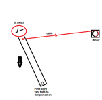
Tilt switch on length of wood/aluminium, slowly descends - constrained by tightness of pivot point. Motor 'cable' / string pulls it back up.
(Model may need resetting / setting in motion every time!)
May need refining
Rampz
Well-known member
Phil yep i understood that to be the case, do you think windscreen-wiper motors are ever driven PWM? would be trial and error i guess to get that right, PWM drive wasn't something that could be done previously, but can with the picaxe.BTW - the code above was pseudo-code, rather than anything practical.
We are driving using a mosfet so PWM would work
My project designs to date have been to keep replacing the old with updated new, my current picaxe pcb replaces the previous 555 setup and does other things like stall protection and low voltage protection, i can see going away from backwards compatible, use something like a 14m2 since i had used all 6 pins already on the 08m2, then i can add PWM and this alternating pulsed DC if we still think this is of use.
The 400ms is what i was told was needed and what previously they had tried to get.
Regards PWM they currently use 2 different motors for torque reasons, some clocks need a lot of tention to run.
For the chimes the motor runs very often during each 15 minute section more so depending on what hour it is.
Last edited:
Rampz
Well-known member
Current motor because it is geared doesn't free run, in fact it can't be turned by hand, maybe a spring where you have an arrow, and allow the motor to wind and unwind the stringView attachment 25182
Tilt switch on length of wood/aluminium, slowly descends - constrained by tightness of pivot point. Motor 'cable' / string pulls it back up.
(Model may need resetting / setting in motion every time!)
May need refining
I assume this is for tilt switch testing?
David_Reynolds
Well-known member
If they were trying to extend the pulse then it would have been better to have increased the resistor to a 280 R the cap could have stayed as was or even greater say up to 220 UF and the gate pulldown say 2.2K would have extended the gate on time tremendously without any kind of welding taking place. doing that would mean though that the mosfet would not be switched off correctly and would at the beginning and end of the cycle become for a while a potentiometer, not good if you are a heavy current carrying transistor.
Avoid that sort of area, at all cost unless you control it to within the limits of the mosfet.
Now I don't quite get what you are using the 555 for, I thought it gave the output for the mosfet and drive motor from the activation of the tilt switch .
I still blame it on the drugs.
Is you test rig really that jittery?
So much so that you cannot either smooth it.
What! 0 . 4 seconds to do the rewind , for a 15 min runtime ?
Why?
What is wrong with taking a few leisurely seconds to wind up.?
David_Reynolds
Well-known member
View attachment 25182
Tilt switch on length of wood/aluminium, slowly descends - constrained by tightness of pivot point. Motor 'cable' / string pulls it back up.
(Model may need resetting / setting in motion every time!)
May need refining
David_Reynolds
Well-known member
Hmmmm. Looks very close though Phil!
PhilHornby
Senior Member
Yes.Current motor because it is geared doesn't free run, in fact it can't be turned by hand, maybe a spring where you have an arrow, and allow the motor to wind and unwind the string
I assume this is for tilt switch testing?
The experimenting's the fun bit!do you think windscreen-wiper motors are ever driven PWM? would be trial and error i guess to get that right
Somewhere in this forum are my adventures with a fan heater motor, that I wanted to slow down. I got there in the end
David_Reynolds
Well-known member
In fact only needs a recoil spring and you have cracked it!!View attachment 25182
Tilt switch on length of wood/aluminium, slowly descends - constrained by tightness of pivot point. Motor 'cable' / string pulls it back up.
(Model may need resetting / setting in motion every time!)
May need refining
PhilHornby
Senior Member
Or a weight ?Current motor because it is geared doesn't free run, in fact it can't be turned by hand, maybe a spring where you have an arrow, and allow the motor to wind and unwind the string
Rampz
Well-known member
They tried various combinations but couldn't get it right, they were often burning mosfets out too, the gate pulldown resistor was set at 3.9k, as you say the mosfet possibly was slightly on would give a reason for burning them outIf they were trying to extend the pulse then it would have been better to have increased the resistor to a 280 R the cap could have stayed as was or even greater say up to 220 UF and the gate pulldown say 2.2K
The 555 allowed me to set the "on" time and disregard any unwanted false triggers from the tilt switch, the current on the tilt switch was very low too.Now I don't quite get what you are using the 555 for, I thought it gave the output for the mosfet and drive motor from the activation of the tilt switch
I use 2 slightly different 555 timer setups, first is monostable, gives a long debounce ignores all bounces, won't retrigger during on time.
Second circuit like above but if i was still getting pulses within the on time then the on time would be extended to 400ms after last pulse, these were used on the chimes side where it needed to trigger multiple times, if i used the first type it would stop
test rig is not so jittery but i can feel it and we don't get that on a clock, it was just a thought.Is you test rig really that jittery?
So much so that you cannot either smooth it.
What! 0 . 4 seconds to do the rewind , for a 15 min runtime ?
Why?
What is wrong with taking a few leisurely seconds to wind up.?
0.4 seconds to move the 15 degrees back to the start position, and add tention to the spring
A few seconds would only be possible with PWM which we didn't have access to in previous set up
David_Reynolds
Well-known member
Rampz, if you end up putting a Picaxe in place as an upgrade then an extra tilt switch might be put in the control box such that if the switch is ignored then a few minutes later it operates. so that if the clock misses a pulse it is invoked by the CPU and can be flagged by an LED.
Just as backup plan.
Doh! I still blame it on the drugs!
Just as backup plan.
I thought we were getting away from those?Or a weight ?
Doh! I still blame it on the drugs!
Rampz
Well-known member
Aside from the test rig i have a test turret clock that is driven by a tilt switch into a 555 circuit, i will build a 14m2 as an interface between the tilt switch and the rest of the circuit, i don't want the original circuit to see any differences or i won't know whats going on, i will allow the tilt switch to be connected in 2 ways so it can be direct on a pin and an alternating pulsed DC as hippy surgested, i can use a spare pin for PWM drive so we can slow the motor when winding up, this will be ok on the clock side by where the chimes get driven from its on most of the time when the clock is chiming, i don't have much space to slow it down before it falls behind, if you know what i mean, but still something could be done.
I have just had a look at my circuit for a picaxe to replace the 555, hoping that the pin that i use to drive the mosfet was a PWM pin seems its not but i can alter the circuit and re produce the pcb's to allow this, i guess i can just send PWM signal direct to the mosfet in the way i currently send an on signal? Never done anything with PWM
I have just had a look at my circuit for a picaxe to replace the 555, hoping that the pin that i use to drive the mosfet was a PWM pin seems its not but i can alter the circuit and re produce the pcb's to allow this, i guess i can just send PWM signal direct to the mosfet in the way i currently send an on signal? Never done anything with PWM
David_Reynolds
Well-known member
The torque as got to be tremendous. so the gearing is way to high, as though they were of the shelf parts.
But if you are talking DC motors then they would operate down to less than a third of their nominal voltage easily.
So if you can find a way to put a DC chopper on the input, there are plenty of cheap adjustable motor drivers available.
They are basically a PWM voltage regulator. you could set on up as a black box off of the twelve volt battery.
You also mentioned the mains going off , and just a thought what about a small solar battery charger.
Yes I get it on the chimes, they need racking on and off quickly due to the amount of energy used to run them.
I will bet though they are not run when under battery power only.
I am rambling now.
Rampz
Well-known member
Dave they will run for a week or 168hr from a 12v 10ah lead acid battery during mains fail.I will bet though they are not run when under battery power only.
I just assumed for PWM i would be switching the mosfet on and off quickly?
The motors are off the shelf in Spain and are DC
David_Reynolds
Well-known member
I will keep on doing it a bit more.
Mind races a bit, if you are going to try reverse logic see if the prog can be done such that on close the tilt is first monitored in one direction, this will then hold the ball until it cannot hang on any more.
After this reverse the current flow and this will help with electrolytic and give the added benefit of a cleaner break.
Do this for alternate cycles.
Yes the DC chopper boards run at around 200KHz
Just a rambling thoughts, once you have your new hardware in place you do not want to have to keep updating anything except the program.
Rampz
Well-known member
Dave yep thats the problem at the moment i have 2 directions, the future of the product and problem solving at the moment, and a growing list of things to tryJust a rambling thoughts, once you have your new hardware in place you do not want to have to keep updating anything except the program.
David_Reynolds
Well-known member
Daft questions. Does the tilt switch drive the motor ? Or does the timer drive it?
I cannot help but wonder why anyone would extend the opening of the original switch unless it was to extend the run of the motor.
I cannot help but wonder why anyone would extend the opening of the original switch unless it was to extend the run of the motor.
Rampz
Well-known member
Attached is my circuit for my interface for testing current built units allowing me to code the interface, there are 2 different sets of connections to allow me to try both setups, will run from 12vdc supply and give a switched output
Attachments
-
48.4 KB Views: 6
Rampz
Well-known member
Dave Tilt switch triggers timer, timer triggers motor via n-channel mosfet, they don't want the motor spluttering about so extend the ontime to even out the way the motor worksDaft questions. Does the tilt switch drive the motor ? Or does the timer drive it?
I cannot help but wonder why anyone would extend the opening of the original switch unless it was to extend the run of the motor.
David_Reynolds
Well-known member
OK. Seems to be more reasonable,. It also means that your tilt only needs to reliably trigger the timer, " microamps" so all you require a snap action on the switch rather than a dithering about which may or may not trigger the timer.
I will mull over that one.
The motor DC motor drivers are quite cheap most expensive part may be a plastic box to put it in But will need to know your amps out to the motor, to be able to point one out to you.
Just looked at your new sketch,
Which pins are the supply pins to the switch and which are the input pins,
I ask because I can see that there are 10K limiters on 2 of them and you have a pulldown on pin 8 don't forget to place a holder on it for alternative pullup from same pin to plus Vs.
Apparently the pins do not like to float and can trigger between as little as 1 and 3 volts.
Any input should be pulled up or down according to the way you wish to use it, if has a floating situation, where it might be open circuit, even if you are plugging parts in or out, that might cause it to operate randomly.
Any positive coming out of a pin or negative going in should just to protect CPU be limited through a load limiting resistor,
I know that it might say that they are protected by internal controls but I never believe it.
Since I do not know what is what from the pic , my own mind says one ( phase ) pin goes either high or low to the switch (via a limiter) it goes into one side of the switch, and out of the same side as well as across the switch ( if it is closed) . both pins from the ends of the switch should have either pullups or pulldowns fitted (10K ) .
If switch is closed then both pins stay high (or low if that is the way the phase pins are driven).
After a short time the current is switched off of phase1 pin and switched on phase 2 pin ( via a limiter again 330R maybe) this then appears on the opposite side of the tilt switch . If still closed then both inputs from switch ends appear to be the same.
The process returns, but if the switch opens for any reason (including a break in a the wire) then the input pins will differ one will have the driver Vs on it the other will be pulled up or down accordingly.
I say all this is the way I see it happening , but Phil or Hippy might have a different Ideas.
I will bow to their skills on the use of it.
Rampz
Well-known member
Dave if you have a look at Hippy's post number #74 the pins b1 to b4 are along the lines of his sketch and the code to go with it, i am just copying it.Which pins are the supply pins to the switch and which are the input pins,
For his sketch all pins float until they are used in the code, they go from input to outputs when needed, don't think you can use pullups in the normal way, so for each cycle that the switch is tested the polarity is reversed by making 2 input pins, outputs each time, each time 1 of the 10k's is used in turn, maybe Hippy will give more info on this?
There are times when pins are used in 3 states, i think a recent post by erco was using that setup for driving multiple led's from a minimum of pins, its called "Charlieplexing"
Pin 8 is used as an alternative way to use the tilt switch, for this it would be moved to the second tilt switch position
I have included a LED so i can see the status of the switch at any time, so if the tilt fails we can see its state etc
Last edited:
PhilHornby
Senior Member
That could be quite advantageous, as far as a test rig is concerned. I thought it might be difficult striking a balance between the arm descending very, very slowly - and it not moving at all.Current motor because it is geared doesn't free run, in fact it can't be turned by hand...
Try this one
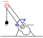
Just an aluminium arm attached to the wiper motor drive square. Adjust the mass, until the arm descends at a rate that you see in the real world. You can then see what a 400mS blast of full motor does to the mass. If it fires up in the air and wraps itself around the tilt switch, I'd suggest some PWM control is in order to tame it
. If it barely twitches, then maybe ON/OFF motor control is fine, after all ...Personally, I don't think you'll need to go to such lengths ... I reckon it's just the un-repeatability and lack of snap ON/OFF action that's causing the issues. Depending on when exactly it triggers, maybe 400mS isn't always long enough - even though most of the time it is.I will allow the tilt switch to be connected in 2 ways so it can be direct on a pin and an alternating pulsed DC as hippy surgested, I can use a spare pin for PWM drive so we can slow the motor when winding up, this will be ok on the clock side by where the chimes get driven from it's on most of the time when the clock is chiming, I don't have much space to slow it down before it falls behind, if you know what I mean, but still something could be done.
I wonder if 400mS is the magic answer, because it's less than half a pendulum swing ... and it's do with how long power can be removed from the "going train" (see, I'm learning too!) before the clock stops? (In which case, Power/pause/power might be needed)
I think you've found the cause of the MOSFET issues of the past though.
PWM is bread-and-butter stuff for the Picaxe - lots of expertise in using it on here! (Being on the 'wrong' pin might not be an issue ... there are ways to twiddle things behind the scenes (viaI have just had a look at my circuit for a picaxe to replace the 555, hoping that the pin that i use to drive the mosfet was a PWM pin seems its not but i can alter the circuit and re produce the pcb's to allow this, i guess i can just send PWM signal direct to the mosfet in the way i currently send an on signal? Never done anything with PWM
pokesfr) that might help).My feeling about the current tilt switch, is that you either trigger the motor
- from the first detection of a change of state
- a fixed time after the first detection
- or when it's been solidly activated, for a set time.
I can't wait for phase 2, where it has to look after three tilt switches and three PWM motor outputs
Good luck to the next bunch of clock repairers, that come along in a 150 years and wonder how on earth it all works!
Last edited:
David_Reynolds
Well-known member
Rampz.
Thanks for that, I have had a look at it and I see what it is doing, novel idea. I see the changes from plus to minus on each side of the switch thro the 10Ks and if both 1 and 2 are kept low it is still closed .
so the time that the test pins are floating is minimal , while the switch is closed, when it opens the far side from the plus is still low , being pulled that way, but the pin on the other end of the 10K resistor gets to go high, denoting an open circuit.
At which point the timer is engaged , or the drive runs until it hits a second switch. All looking good.
And if anything does go wrong it has the total limit switch to fall back on.
As for LED driving, driving pseudo AC controlling from 2 switches and PWM from it really all these things at the same time from a 14 pin Picaxe chip, enough already.
These are one for each winder unit aren't they?
David_Reynolds
Well-known member
Also the magnetic position sensor seem to be something to consider instead of the tilt switches for your new builds.
If you lose position on that just reset the system and start again.
If you lose position on that just reset the system and start again.
Rampz
Well-known member
Thanks Phil for ongoing ideas, the arm only wants to move through an arc of 15 degrees and needs to do that over a 15min period thats the hard bit its moving just so slowly, going to be a really fine balance, not sure i can drive the motor slow enough in the weight direction.Adjust the mass, until the arm descends at a rate that you see in the real world
i want to cover all bases if i am making a test pcb, i don't want to jump any further with a complete design until i can find more out about the cause, the current test rig has at least found that there are multiple triggers from the tilt switch, i had worked out there was sometime a second one, but we know that without contact bounce pause there can be upto 7 bouncesPersonally, I don't think you'll need to go to such lengths
if you look at my previous thread "switching issues" last post #82 you can find my current code for the picaxe circuit, in post #50 you can see a pic of the control box with a small sub board that has the 08m2, i need to alter the code to suit the 3 thoughts you have above, have a look see what you think? Currently its 400ms after the last pulse i think, assuming all the pulse are within 400ms of each other, if the pulses are slower than 400ms then it will drive twice as is needed on the part of the clock that drives the chimes.My feeling about the current tilt switch, is that you either trigger the motor
Whichever gives the most repeatable result.
- from the first detection of a change of state
- a fixed time after the first detection
- or when it's been solidly activated, for a set time.
Regards pins on the 08m2 for PWM currently the motor is controlled by pin C4 which currently does have PWM ability?
Rampz
Well-known member
Dave i am already doing more than this with a 08m2, so driving an led to mimick what the switch is doing must only be a few extra lines of code, look at my previous thread "switching issues" last post #82 you can find my current codeAs for LED driving, driving pseudo AC controlling from 2 switches and PWM from it really all these things at the same time from a 14 pin Picaxe chip, enough already.
Yes i am still interested in this too i hope to have a chat with the manufacturer this week and get some direction before i spend too much money for him, i just need to get him on board, at least we all have some great ideasAlso the magnetic position sensor seem to be something to consider instead of the tilt switches for your new builds.
Rampz
Well-known member
Phil you laugh but my thread "Vmusic2 cockrill" is possibly the start of something exactly like that, its a project where there are multiple motor, i have not seen the project yet, but i started the tread because one item that was required was the playing of a cockrill track as required and wanted to be sure it could be doneI can't wait for phase 2, where it has to look after three tilt switches and three PWM motor outputs
PhilHornby
Senior Member
I wasn't expecting the motor to have to be driven in reverse - with an appropriate mass, gravity should do the work. The aluminium arm will act as a lever, reducing the amount of mass required.the arm only wants to move through an arc of 15 degrees and needs to do that over a 15min period that's the hard bit its moving just so slowly, going to be a really fine balance, not sure I can drive the motor slow enough in the weight direction.
The base pic (PIC12(L)F1840) has a PWM module that can be 'steered' to C.4, but the Picaxe firmware only allows control of the one on C.2.Regards pins on the 08m2 for PWM currently the motor is controlled by pin C4 which currently does have PWM ability?
Here is some code that tells the Picaxe to use the other PWM module (which by default, inconveniently outputs to C.0).
I'm aware that this code will probably read like a 'magic spell' - it needs to be read in conjunction with the datasheet for the base pic.
(The
pwmout statement is standard 'Picaxe Basic' and would need adjusting to suit the motor).
Rich (BB code):
#picaxe 08m2
#no_data

symbol APFCON  = %01011101          ;$11D - Alternate Pin Function
symbol PSTR1CON= %10110110          ;$296 - PWM Steering Control Register
symbol CCP1SEL = bit0
symbol P1BSEL  = bit1


;
; Use 'sfr magic' to start PWM on PinC.4 (this is not normally allowed by Picaxe firmware)
;
; We can redirect PWM P1B to RA4/C.4, rather than RA0/C.0 (where it doesn't work on Picaxe)
; Then we can configure PWM to use P1B on that pin.
;
      peeksfr APFCON,b0
      P1BSEL = 1                    ;P1B on RA4/C.4 instead of default RA0/C.0
                                    ;See description of Register 12-1, Page 99
                                    ;of PIC12(L)F1840 datasheet
      pokesfr APFCON,b0
;
; Now reconfigure PWM to use P1B.
;
      pokesfr PSTR1CON,%00000010    ;Steer PWM to P1B (only). Steer ASAP (STR1SYNC=0)
                                    ;See description of Register 24-4, Page 181
                                    ;of PIC12(L)F1840 datasheet
      pwmout pwmdiv64, C.2, 124, 249;Start PWM output = 1000Hz at 50% (@ 32MHz)
      output C.4                    ;Allow the P1B PWM signal out on RA4/C.4
                                    ;It now starts on C.4, despite that earlier *REQUIRED* reference to C.2!
                                    ;pwmout clearly just expects PSTR1CON to be in default state...
Rampz
Well-known member
Looking for on-axis and off-axis magnetic position sesnor with analog output, best i can find is the MLX90371, actual part number being MLX90371GDC-BCC-300-SP maybe rq3 will have 5 mins to see if he thinks its suitable? It does seem to support both on-axis and off-axis planar detection and seems to be analog output, they do also do a development pcb with one attached which could be useful to play about with.
The analog output is 10%-90% vdd, they do an evaluation board with a chip pre mounted its part number is EVB90371-GDC-300-Rev1.0
https://www.melexis.com/en/product/evb90371/evaluation-board-mlx90371 is the webpage for the board and it gives a circuit digram from the board looks like it will go straight into a adc terminal on the picaxe?
Last edited:
Rampz
Well-known member
Phil yes looks like magic code, i would say i'm better altering my pins to allow the use of C4, since i am already usings C0, Oh and read the 382 page manual, thats some manualI'm aware that this code will probably read like a 'magic spell' - it needs to be read in conjunction with the datasheet for the base pic.
PhilHornby
Senior Member
ProbablyI would say I'm better altering my pins to allow the use of C4 ...
(Though just to be clear, C.2 is the only PWM output pin directly supported by the Picaxe firmware).
My feelings too. Basically what there is works when it works, just that there seems to be a potential failure in the tilt switch, tilt switch activation, or the detection of that activation.Personally, I don't think you'll need to go to such lengths ... I reckon it's just the un-repeatability and lack of snap ON/OFF action that's causing the issues. Depending on when exactly it triggers, maybe 400mS isn't always long enough - even though most of the time it is.
The root problem seems to be that the tilt switch isn't snap-on and snap-off and that could never be guaranteed with the physics of what we have.
The solution seems a better tilt switch, something solid state that can determine exactly how far it has been tilted. Perhaps something like the ADXL345.
Rampz
Well-known member
I just wonder if the very very slow speed that i am tilting will it will sense it or not, the motor on the chiming side of the clock don't move at all till the clock chimes i'm quite sure it would pick up movement very well, just the clock side that might struggle as may any kind of sensor, i have ordered a few of the items in post #155 and an evaluation board all for £40 so will be a startPerhaps something like the ADXL345
Last edited:
Rampz
Well-known member
Ok i have revised my interface board i have removed the alternating pulsed DC setup, since the general feeling thats its over kill and unlikely to be the reasons for failure in the short term anyway.
I have added a PWM output on C2 and have included a 10k pull down resistor to ground to go to a n-channel mosfet if required.
I have added a ADC input to be used with my magnetic evaluation board i have ordered on C1 also with a 10k pull down resistor to ground.
Mimic LED is on C0 i know it will flicker during programing and any info being displayed on the terminal, but with all that removed should be ok.
I have extended the 5V from the regulator to a terminal block to run the evalution pcb
Tilt switch is on C3 with 10k pull down to ground
The switched output goes to a relay via a transistor from pin C4
Hopefully this setup will allow me to try different setups etc.
This thread is getting rather long, i guess i have been repeating myself rather a lot
Any thoughts or am i boring everyone now?