Hi Guys,
I am absolutely new to this stuff, I know a bit about the basics in electronics, a lot about logic circuits, and even more about programming.... but as you can read, there is a shortcoming when it comes to the more advanced stuff in electronics, that's why I do need your help.
I recently purchased the Picaxe Microbot starter kit (as I thought that this would be an ideal platform to learn the basics, and to grow further from there). In combination with an SRF005 a servo a brandnew Picaxe 18x, and two Sharp GP2D12 infrared range sensors. Nice little toys and they all do work perfectly. But I have a problem since the very beginning that I have received the board. One of the two DC motors didn't do anything at all. I first blamed myself, by claiming it would have been a result of sloppy coding. But that didn't really seemed to be the case.
As I went through all possible options (broken DC motor, etc), I started by taking my trusty multimeter into my hands, and messured through all the ports that are going out to the L293D Motor driver. And I see something really strange:
picboard.jpg
To give you a raw idea about the deltas between the original board and my modified setup:

*Position R-2 carries a 330Ohm resistor.
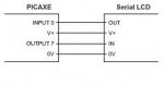
*The V+ and GND of Out 2 are connected to a small servo
*Out 2 is directly connected to the control of this servo (so there is a 330Ohm resistor between them) and the servo works fine
*The SRF005 is directly hooked up to the SRF004 terminal, and works fine.
*the V+ and GND of Out 1 and 0 are hooked to the Sharp sensors in order to feed them.
*the In 1 and 2 terminals are hooked up to the output of both sharp sensors for ADC, and seem to work without any problems.
That's about it. But now to my problem:
One of the two DC motors (as a drive) is not working. If I messure Out 1 and Out 2 of the LD293D I get a steady current of approx 4.2 volts and that seems to do the job driving the little motor when active.
The other end of the LD293D doesn't seem to do that much, if active, it only gets to approx. 0.11 volt..
If I go further down the chain the PWM Out6 offers me the desired 4.2volt the Out 4, again only something between 0.11-0.5 volts.
On the Picaxe 18x itself out 5 is showing the same symptoms!!!.... Then my new 18x became my suspect, and I replaced it with the included Picaxe 18... but still the same issue. (which makes me beleive that my PIC is ok). Please also do remember the followin: The problem did occur way before I started to solder my own material onto the board.
Can this be caused by a broken capacitor (not charging correctly), or do you guys think that either the PWM, or the LD293D are busted... and if, how can I test / troubleshoot this?
Many thanks!! All help will be really appreciated!
With kind regards,
Gereon
-Amsterdam
I am absolutely new to this stuff, I know a bit about the basics in electronics, a lot about logic circuits, and even more about programming.... but as you can read, there is a shortcoming when it comes to the more advanced stuff in electronics, that's why I do need your help.
I recently purchased the Picaxe Microbot starter kit (as I thought that this would be an ideal platform to learn the basics, and to grow further from there). In combination with an SRF005 a servo a brandnew Picaxe 18x, and two Sharp GP2D12 infrared range sensors. Nice little toys and they all do work perfectly. But I have a problem since the very beginning that I have received the board. One of the two DC motors didn't do anything at all. I first blamed myself, by claiming it would have been a result of sloppy coding. But that didn't really seemed to be the case.
As I went through all possible options (broken DC motor, etc), I started by taking my trusty multimeter into my hands, and messured through all the ports that are going out to the L293D Motor driver. And I see something really strange:
picboard.jpg
To give you a raw idea about the deltas between the original board and my modified setup:
*Position R-2 carries a 330Ohm resistor.
*The V+ and GND of Out 2 are connected to a small servo
*Out 2 is directly connected to the control of this servo (so there is a 330Ohm resistor between them) and the servo works fine
*The SRF005 is directly hooked up to the SRF004 terminal, and works fine.
*the V+ and GND of Out 1 and 0 are hooked to the Sharp sensors in order to feed them.
*the In 1 and 2 terminals are hooked up to the output of both sharp sensors for ADC, and seem to work without any problems.
That's about it. But now to my problem:
One of the two DC motors (as a drive) is not working. If I messure Out 1 and Out 2 of the LD293D I get a steady current of approx 4.2 volts and that seems to do the job driving the little motor when active.
The other end of the LD293D doesn't seem to do that much, if active, it only gets to approx. 0.11 volt..
If I go further down the chain the PWM Out6 offers me the desired 4.2volt the Out 4, again only something between 0.11-0.5 volts.
On the Picaxe 18x itself out 5 is showing the same symptoms!!!.... Then my new 18x became my suspect, and I replaced it with the included Picaxe 18... but still the same issue. (which makes me beleive that my PIC is ok). Please also do remember the followin: The problem did occur way before I started to solder my own material onto the board.
Can this be caused by a broken capacitor (not charging correctly), or do you guys think that either the PWM, or the LD293D are busted... and if, how can I test / troubleshoot this?
Many thanks!! All help will be really appreciated!
With kind regards,
Gereon
-Amsterdam