Just a quick question regarding unused input/output pins, do they have to be tied to ground if unused.
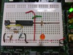
I have been building all my test circuits on the AXE091 picaxe development board with no problems all working ok. But if i build the same circuit on breadboard they don't seem to work?
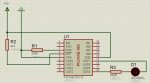
The Pic18x code is as follows: (Receiving serin data from a PIC40x1 (Interupt) on the AXE091 Development board via Pin17 (in0))
As I said works when both Picaxe's are connected via the AXE091 development board, but when the Pic18x ir removed from the development board to its own circuit nothing...
PowerOnReset:
setint 1,1
MainLoop:
if b0 = 1 then gosub LEDOn
if b0 = 0 then gosub LEDOff
goto MainLoop
Interrupt:
serin 0,T2400,b0
setint 1,1
return
LEDOn:
low 7
high 4
pause 1000
low 4
high 7
pause 1000
return
LEDOff:
low 4
low 7
return
Led is BiPolar hence why pin 10 and 13 are used.
I have been building all my test circuits on the AXE091 picaxe development board with no problems all working ok. But if i build the same circuit on breadboard they don't seem to work?
The Pic18x code is as follows: (Receiving serin data from a PIC40x1 (Interupt) on the AXE091 Development board via Pin17 (in0))
As I said works when both Picaxe's are connected via the AXE091 development board, but when the Pic18x ir removed from the development board to its own circuit nothing...
PowerOnReset:
setint 1,1
MainLoop:
if b0 = 1 then gosub LEDOn
if b0 = 0 then gosub LEDOff
goto MainLoop
Interrupt:
serin 0,T2400,b0
setint 1,1
return
LEDOn:
low 7
high 4
pause 1000
low 4
high 7
pause 1000
return
LEDOff:
low 4
low 7
return
Led is BiPolar hence why pin 10 and 13 are used.
Attachments
-
 93.9 KB Views: 32
Last edited: