pulsin then servo

alband

Senior Member
Relevant bit:
The PID controller calculation (algorithm) involves three separate parameters; the Proportional, the Integral and Derivative values. The Proportional value determines the reaction to the current error, the Integral value determines the reaction based on the sum of recent errors, and the Derivative value determines the reaction based on the rate at which the error has been changing. The weighted sum of these three actions is used to adjust the process via a control element such as the position of a control valve or the power supply of a heating element.
By "tuning" the three constants in the PID controller algorithm, the controller can provide control action designed for specific process requirements. The response of the controller can be described in terms of the responsiveness of the controller to an error, the degree to which the controller overshoots the setpoint and the degree of system oscillation. Note that the use of the PID algorithm for control does not guarantee optimal control of the system or system stability.
Can a PICAXE do this?

This has some algebra that could be copied.
 

eclectic

Moderator
alband.

Re the compass module you mentioned in an earlier post.

If you search the Forum, I don't think anyone has (yet)
sorted out the interfacing.

e
 

alband

Senior Member
Yeah, I found that document lasted posted by west I think.
I'm guessing though that since the originator hasn't replied, he's go it working wit that code.
I ask him in that thread.
 

alband

Senior Member
It's big, but it's flat so thanks. :)
Have you used one?
Would it be effected buy magnets such as motors?

Anyone any ideas on the PID/PICAXE thang?
 

alband

Senior Member
Do you currently have it set-up?
If so, do motors have much affect on it e.g. a servo about 1cm away.

BTW was anyone watching that Einstein Eddington thing just now?
If not and your into physics; watch it on iPlayer!
 

westaust55

Moderator
I also have the CMPS03 compass module.

Found that I could not calibrate it through the i2c method as supposedly could and seems no-one else has tried or managed either. Everyone can calibrate with the switch/contact method.

It is recommended that you keep motors at least 250mm from the CMPS03 motor. Larger motors may have stronger magnetic fields so further would always be better.

I have mine mounted in a separate box for when I want to use it and all bolts are nylon for the CMPS03 and another small electronic board driving 16 LED's as a pseudo compass indicator on the same box.

See:
http://www.picaxeforum.co.uk/showthread.php?t=9904
http://www.picaxeforum.co.uk/showthread.php?t=9852
 
Last edited:

alband

Senior Member
Just an added though about that compass;
Study this picture of it: http://www.active-robots.com/products/sensors/sensors-details-6.shtml
It uses a PIC16F872 which is what we get our 28X from I believe (waiting for a technical correction there). The other two big chips are these:
http://search.digikey.com/scripts/DkSearch/dksus.dll?KeywordSearch
and this is the datasheet:
http://www.nxp.com/acrobat_download/various/SC17_GENERAL_MAG_98_1.pdf
Could a PICAXE read the data from the KMZ51 directly instead of another PIC reading it and then sending it?
 

alband

Senior Member
So it is pretty stongly effected by anything metal and especialy magnets:(
That kinda rules out using one to use as a lateral gyro for the turret rotation then.
Any other ideas how this could be achieved?
Anyone know what they use in the real beast; GPS, Sat-Nav?
 

westaust55

Moderator
Exact wording I received from Gerry at Robot Electronics (manufacturers of the CMPS03) some months ago was:
You need to keep the compass away from magnets, for example speakers and motors. The compass on our test robot is around 250mm from the motors and that's fine. You should also try to keep it away from ferrous materials, however ferrous materials that are fixed relative to the compass can be compensated to some extent by the calibration.

The compass FAQ at http://www.robot-electronics.co.uk/htm/cmpsqa.shtml should also be helpful.
 

alband

Senior Member
I have several magnets in the turret round the edge to keep the top half in place.
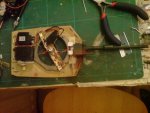
The servos in the picture have now been ripped out and I am going to use the smaller one for the gun elevation just to the right of the gun. It doesn't fit there as-is, so I have taken the POT out and am going to re-solder it the other way round so that I can mount it on the other end of the axle.
The inner gear isn't ferrous and neither is the piece of brass that the headphone jack is mounted on. Unfortunately the metal strengthening rod that runs down one edge of the brass is ferrous.
Do you think calibration could sort this out?

Re post 79 (must have missed it). I don't see how a gyro in the hull could work and not even sure whether one would fit.
 

Attachments

BeanieBots

Moderator
Just gone over yesterday's posts.
PID with PICAXE? Yes, but not with the bandwidth you would require.
Gyro size? Much smaller than ANY compass solution. Much smaller than ANY PICAXE/accelerometer solution.
A "sensor(s)" in the hull COULD work in THEORY but I'd have no idea how you would get a PC to do the required sums let alone a PICAXE. You'd also need all the information regarding turret to hull position.

Model helicopters use the smallest lightest technology available. I have one which is 150mm long and weighs only 49g. It has full "heading hold" lock which uses a solid state gyro. If you can make one smaller or lighter, you can make yourself a small fortune. I don't want to put you off trying except to say that the "big boys" have invested millions on it already and have produced a product which does the job as small and as light as they possibly can. Trying to make your own is almost like trying to make an IC from descrete components so that you get even smaller than the chip you are trying to replicate.

EDIT:-
Is that picture the turret?
You could fit about 5 gyros in there!!!
Use a slightly smaller servo and there's room for another radio as well.
It might even be possible to get a gyro in the "fatter" portion of the barrel. Deffinitely in the portion where the barrel is fixed to the turret.
 
Last edited:

alband

Senior Member
Gyro's are sooo expensive, but I confess I don't know much of them and I've found that searching "gyro" is about as useful as searching "the". Any sites you know that are good for gyro range?

My thoughts precisely about a sensor in the hull; possible but difficult.

I'm sure though I'm going to use that accelerometer for the gun elevation and am set on that's workings, I'm just not sure about the turret rotation.

EDIT re: Flat, Flat, Flat, Flat. The hull is less that 1cm tall (1/35 scale). The length of the turret alone is 12.5cm, sorry 125mm.
I've found some gyro's that would fit, but they are flat when mounted the wrong way. That barrel is less that 8mm inside and is stuffed full of laser. :D

Like I said though, I've never really done gyros and even thought the ones I've found wouldn't work can you show me some examples of one's you reckon would.
 

BeanieBots

Moderator
Firts off, I don't think you are going to find anything under £20.
You should search for "RC gyro". I honestly don't think you could make anything cheaper.
You DON'T want any that even support let alone are specific for digital servos. That would be expense for no reason.
Ideally, you want "heading hold". That is similar to "rate" but the position error is integrated over time to give ZERO position error. A "rate" gyro will only minimise error. Naturally, "heading hold" will be more expensive.
Any decent site will give the dimensions and weight. That is just as important in helis as it is in your app. Again, smaller = more expensive. You DON'T need RC gain control or dual rate.

The first thing anyone in the micro aircraft hobby does, is to remove the casing. That can save a lot of weight AND size. How much size gain is pot luck unless you know somebody who has already done it with the EXACT one you pick. The biggest part is often the connectors. Remove them and wire direct.
 

InvaderZim

Senior Member
Re: gyro in the hull.

I'll go over the idea again. I'm assuming that the controller in the hull is sending position data to the turret. For this to work with rotation only, you can mount the gyro *in any location in the hull* (it doesn't have to be directly under the turret; it could be behind the headlight or anywhere). Let's say that 0 degrees is straight ahead, and the hull sends the turret a command position of +/- 180 degrees.

So start off with a gyro in the hull, and the turret pointed at 0 degrees. At that point, the gyro will record the hull rotation as 0 degrees also.

Now if the tank hull rotates, it will do a gyro reading again. Aha, it says, I've rotated +30 degrees! Now it must send a command to the turret to rotate -30 degrees from the current position to compensate.

If it is taking readings and sending commands frequently enough, then the turret should be able to reasonably maintain the starting position of 0 degrees.

Now for the next bit: say you want the turret to rotate (a reasonable task for a tank!). You've already got the turret "setpoint" at 0 degrees. As you get a command to "turn turret" you'll increment or decrement the setpoint. When you do a gyro reading, you'll compare the hull reading to the setpoint, and instruct the turret to move accordingly.

The maths for rotation are straight-forward, you just compare the rotation of the hull (in 2-D) to the rotation setpoint of the turret (in 2-D). Depending on how the gyro works, you might need a square root function, which you get with an X1/X2 part.

When it comes to barrel tilting, things will be a bit trickier. You have to account for the offset from the gyro and the barrel's pivot point (which is not the same as the center of rotation of the turret), which is where you get to tricky maths (in 3-D). Things might still be simple though if you position the gyro in a good spot, like right under the turret.

Again, the rotation aspect seems pretty doable (no harder than doing a gyro in the turret). Another nice thing is your tank knows which way it's going, a bonus if you ever want to have the thing run on auto pilot : )
 

alband

Senior Member
Er, hmm...

I think this is relevant. The turret rotation is controlled by first the Rx, then the ESC then a motor. Adding a gyro would mean this: first the Rx, then gyro, then ESC, then motor. The gyro is designed for servos though not ESC's. Also, I think, if the turret is told to move, this command will be sent through the gyro. If the gyro is in the hull it won't sense the movement and think "The tank must have been moved whilst that command was acting, better send it again to get the turret in the right place". i.e. it would look for itself moving when the command for the turret to move is sent.
I'm not sure...:confused:
BB?
 

BeanieBots

Moderator
The theory is sound, but it assumes you have a gyro which tells you the required information and that a PICAXE can process it quick enough.
The "cheap" RC servos can't do that and a PICAXE is not quick enough even if they did. You've got <20mS in which to do it all.
Although such a gyro is actually simpler than an RC type, they are considerably more expensive due to supply demand.
The RC gyro takes your position pulse as demand, and then adds to that pulse what is required to make the postion remain the same despite any movement made to move it off postion. That is NOT a simple control algorythm.

Saying all that though, most RC gyros have an option to reverse the signals. That might give a option for a hull based gyro but it would need to in line with the turret. I'll try and dig one out to experiment.

Think there might some confusion over terms.
Servo actually means a control loop. Here it refers to a motor and gearbox with a SERVO controller built in. AKA, "Hobby Servo". A heater controller using something like PID control can also be called a "servo".

"Gyro" is more often than not thought of as a mechanical spinning flywheel or possibly one with at least a load sensor to give rate of change of angle. An "RC gyro" is SO much more than that. It includes the control loop for a start.
 

alband

Senior Member
West: d'you think the calibration would be able to get rid of errors from those magnets (post 93)?

Would a gyro work with an ESC?

BB, where are you looking at gyros? - I don't know any "gyroy" sites.
 

BeanieBots

Moderator
Google for "RC gyro". Any of the hobby sites. Same places you'd get RC servos from.
An "RC gyro" cannot work on an ESC signal but I'm not sure how/why that was thrown into the equation. It's servo signal in, compensated servo signal out.
 

alband

Senior Member
Yes, but would be compensated the wrong way.
For a servo, the length of the pulse controls what angle the servo is at. With an ESC, the length controls speed. So a pulse of 1.5ms would not mean "go to 90 degrees", it would mean "don't turn the motor". A pulse of 2ms wouldn't mean "go to 180", it would mean "turn the motor fast".

Edit: I've just searched and as soon as you get anything remotely small, it cost >£40. http://www.heliguy.com/Extras/Gyros/Align-RCE-500/
 
Last edited:

BeanieBots

Moderator
Yes, but would be compensated the wrong way.
For a servo, the length of the pulse controls what angle the servo is at. With an ESC, the length controls speed. So a pulse of 1.5ms would not mean "go to 90 degrees", it would mean "don't turn the motor". A pulse of 2ms wouldn't mean "go to 180", it would mean "turn the motor fast".
No, No, No.
You've completely missed the concept of RC control.
A servo demand pulse, is a servo demand pulse, is a servo demand pulse.
It DOES NOT CARE who, what or where that pulse is to be used. Effectively, it is nothing more than a number. As you know, it is limited to the range 75 to 225. What those numbers mean is 100% defined by whatever receives them. 75 on one servo might mean go fully clockwise. On another servo it might mean go fully anti-clockwise. On an ESC, it could mean stop. On another it could mean full speed. Some ESCs are centered around 150 to give forward/reverse. Others (eg aircraft) only give forward over 75-225 or 225 to 75. Nearly all (except the VERY cheap) Tx units have servo reversing switches to compensate for this.

ALL "RC Gyros" have a reversing switch so the "compensation" can be added or subtracted. Don't get the servo pulses (demand) mixed up with the pulses that come out of an ESC (actual).
If for example you have a "tank" which you want steer in a dead straight line, it is common practice to include a "RC gyro" on one of the ESCs to assist with steering.
 

BeanieBots

Moderator
I've just tried the "RC gyro" in the hull method.
Although the THEORY is sound, I don't think you would ever get it to work in practice.
First off, "heading hold" cannot be used. That is because heading hold uses a full blown PID algoryhtm. The "compensation" will keep adjusting in an attempt to correct the angle of the gyro. (known as integral wind-up).
If you opt for a "rate" gyro, you would need to set the gain such that the "compensation" gives an amount of drive which exactly matches the angular displacement. In other words, open loop control. Without ANY feedback. I tried it. It does at least HELP, but it is far from perfect. Also, something you might not appreciate as you've not played with them, but solid state gyros are very temperature dependant. If you got it perfect one day, it would not be the next.
 

alband

Senior Member
I'm really not sure it would work with an ESC.
Gyro's are designed to work for a servo. You say they will work with an ESC...
Scenario:
Thank is facing North with turret (gun from now-on) is facing North also.
I use the Tx to tell the ESC (via Rx) to rotate clockwise at mid speed until the gun faces East. Once the gun is facing East, I let the stick go back to centre.
The gyro senses that the turret and gun are 90 degrees from where they should be since the stick is back at the centre.
This is one problem. Also a gyro would expect that any commands (without outside interaction) should send it +/-90 degrees. But since I have a turret that goes infinite degrees, it won't understand.

Either it won't work or I don't understand.
 
Last edited:

BeanieBots

Moderator
Well, it DOES work.
I think you might have got little mixed up over what needs to feed the gyro signal.

Two scenarios.
1. Rate Gyro controlling left hand track for assisted steering.
Two ESCs (L & R) , one for each side. Two servo signals (L & R), one for each side.
Signal for RHS goes direct to ESC. Signal for LHS goes via rate gyro.
You move forward but the left track sticks a little and the tank begins to turn. The gyro detects the turn and increases the drive on the left ESC to compensate.

IF you were to pick up the tank and rotate it, the left track would move such that if it were on the ground, it would try to counteract the movement. The use of a "rate" gyro here simply tries to a little correction. It is "proportional" control only.

If you used a "heading lock" gyro and picked up the tank and turned it around, the left track would start to move and KEEP MOVING. It would not stop until you put it back down and the tank had rotated back to the original position. This is because "heading hold" includes an "integral" term in the control loop. In this case, your servo input to the gyro is actually a command to turn, not one to go forward.

With a "heading hold" gyro in the turret, your servo command for turret position tells the gyro the "heading" you want. If you give a stick movement for CW, then the turret will move clockwise and keep moving until you return to neutral. If you now rotate the tank, the gyro will apply whatever servo signal is required to your turret moving servo to keep it on the same bearing. I'm assuming your turret servo is modified for continuous rotation.

This is exactly the same method used on a helicopter to keep the tail pointing the same way. Again, there are two methods of operation. In a "conventional" heli, the tail rotor has a fixed speed and a servo is used to change the pitch and hence the torque. In many small electric helocopters, the tail rotor is fixed pitch and an ESC is used to control the speed and hence the torque.

Hope that all made sense. It DOES work with ESCs. I've done it in both tank steer robots and both types of helicopter described above.
Don't forget, helicopters also go fully around on the spot, just like tanks/turrets.
 

BeanieBots

Moderator
Well, I did the I don't normally do and saved you the bother of looking it up on Google. Quite a simple task really.
Here's what I found:-

Once you have set the Tx menu, you now have to set the Gains to the Gyro. Gains are set by a percentage. What you need to do is set one above 50% for HEAD HOLD MODE and the other below 50% for RATE MODE.
At 50% i found that this is the Gyro's starting points it seems like its not working.

At this stage it would be a good idea to watch this Finless Bob Video
http://video.helifreak.com/?subpath=...=tail_gyro.wmv

This Video is so you that can under stand whats going on with the tail and Gyro because if thats not setup right then you won't be able to set the Gyro to work with the DX6i.

This will be a good starting point, set the Gyro switch on the Tx to the "0" position this will be HeadHold. Then in the Gyro settings on the Tx set the Rate to 65.0% so this puts the Heli into Head Hold mode. Set the rate on the Tx in Gyro setup so that position "1" is 40.0% for Rate mode. These settings should get your Gyro working so that you can start fine tuning it. You need to adjust in small increments.

When the red light is on then its in RATE MODE, When the red light is off its in HEADHOLD MODE and When the light is flashing red the Gyro is INITIALISING.
.

So it would appear that it can be either. It requires another channel to change between modes.
FWIW, 28mm X 28mm X 19mm 11g
 

alband

Senior Member
Thanks :), I searched "EK20704" and found the page with "EK2-0704-B" on it. If I had searched that I would have found your page.
How do I switch channels with the Tx? - Would I need a particular Tx?
 

alband

Senior Member
:D:rolleyes: no, no, no.

I've never used a gyro before and certainly never used a rRx accessory where the mode can be changed from the Tx. This would surely mean that the Rx would need to know what is connected to it and then send this back to the Rx. I don't know of the receiver sending data to the transmitter ;).

FYI, I have a Futaba and the only options it has are Reverse, D/R, E.P.A, Trim, P.MIX, and W.MIX.
 

Rickharris

Senior Member
HI - I havn't contributed to this because gyros etc are outside my practical experience. from my PMs with you I gather you are concerned about size amongst other things s i will answer your questions here in the open forum so everyone can benifit:

"Q ... Those two boards - how are they connected?
Have they both got a sensor?

AAs far as I can see a soldered connector i.e. pins soldered from one board to the othwer
If I had both the sensor board and the other board flat soldered together with some wires, would the sensor still be giving me "yaw" readings or would I get pitch or roll?

AI don't know i although it looks like BB has answered this.


The 2 boards are smaller than the declared case dimentions BUT they are soldered at right angles to each other

Pictures here http://picasaweb.google.com/rickharriss/Gyro?authkey=dAReI7V_D5I#
 

BeanieBots

Moderator
Alband, all your Tx needs to do is send a "servo" signal to the gyro telling it what mode to use. Just like it would tell a "servo" where to go.
The gyro will have TWO connections to your receiver. One to tell it which mode and one to tell the turret where to go.
Hmm, that makes your problem even bigger. ANOTHER signal to get up into the turret:eek:

Rick, thanks for pictures. Shows clearly just how small it could be without the case. Replacing one of the servos with say an HS-55 would free up enough space to fit that gyro.

Not sure how that gyro would behave without the mode select signal. I'd expect it to default to a user defineable setting. Maybe Rick knows.
 

alband

Senior Member
Basically, I have enough room to lie them both flat. But if I lie the sensor board flat, it might measure the wrong axis.

I need to know;
Which axis it measures when it is on the flat bottom?
What orientation the boards are in when it is on the flat bottom? Board with or without wires for reference?
Which board has the sensor?
The casing should say which axis it measures.

Thanks. :)
 

Rickharris

Senior Member
...

Not sure how that gyro would behave without the mode select signal. I'd expect it to default to a user defineable setting. Maybe Rick knows.

Sorry to say the unit has never been powered up as I had no need for my application - I got it as part of a package deal. I know nothing more than has been put in this thread :)

Ignorance is bliss!
 

alband

Senior Member
T6EXA.
It has some mixers.
I needed the V-tail mixer for the tacks but had to use hardware because the in-built mixer didn't give the required results. Also, hardware was tiny and I had it lying around.
P.MIX can be either: Inhibited or on
W.MIX can be either Inhibited, Flaperon, V-tail, Flaperon + V-tail or Elevon.

BTW, Din't worry, yes I turned on my radio to find out but I took out the crystal. Although to be fair, anyone flying near me in this light is doomed anyway. :D
 

alband

Senior Member
Sorry to say the unit has never been powered up as I had no need for my application - I got it as part of a package deal. I know nothing more than has been put in this thread :)

Ignorance is bliss!
Tell me about it! :D

Right. You took the cover off though, yes?
There sees to be from those pictures two main chips. Can you "dicttype" the codes on them?
 

BeanieBots

Moderator
BTW, Din't worry, yes I turned on my radio to find out but I took out the crystal. Although to be fair, anyone flying near me in this light is doomed anyway. :D
We do night flying as well!
Not at my nearest field but the next one down SPECIALISES in it.
You can even get illuminated blades for helicopters:cool:
(battery is in the blade before you ask).
 
Top