pulsin then servo
- Thread starter alband
- Start date
BeanieBots
Moderator
We've already covered how pulsout would work with the correct timing.
Pulsin (and your Rx) sets the frame rate.
Just try it.
Pulsin (and your Rx) sets the frame rate.
Just try it.
BeanieBots
Moderator
Doesn't that confirm that your "interrupt" serin is NOT working then?
If pulsin gets the correct number,
Interrupt serin/serout (according to you) works, then where is the number being made incorrect?
Thanks for helping me be #1
If pulsin gets the correct number,
Interrupt serin/serout (according to you) works, then where is the number being made incorrect?
Thanks for helping me be #1
I know the serial communication is happening but the values are getting mixed up somewhere. This is the relevent code. The second vairable starts as either 0 or 1 but comes out as 11 or 3 respectively, the other variable displays other numbers which I assume are linked to the originals:
Code:
		pulsout 1,10
		serout 1,T2400,(b0,b2)
Code:
setint %10000,%10000

interrupt:	serin 4,T2400,b0,b1
		debug b0
		debug b1
		let b12 = 1 ' ignore this (it becomes apparent if you study the full code in prev posts)
		setint %10000,%10000
returnBeanieBots
Moderator
Something may well be happening, but not what you think.
Forget all that.
Try this:-
Sender:- (just one servo for now)
main:
pulsin pin,b0
serout ... b0
goto main
Receiver:-
main:
serin ... b0
if b0>225 or b0 < 75 then main
pulsout b0
goto main
If that works, then add in the servo.
Forget all that.
Try this:-
Sender:- (just one servo for now)
main:
pulsin pin,b0
serout ... b0
goto main
Receiver:-
main:
serin ... b0
if b0>225 or b0 < 75 then main
pulsout b0
goto main
If that works, then add in the servo.
Well done; you may gloat.
It did work but produced some weird noises.
I tried removing the serial line at different stages and the servo stays put.
Therefore I should be able to get it not to send if the variable is the same?
e.g. (with almost same code at receiving end)
It did work but produced some weird noises.
I tried removing the serial line at different stages and the servo stays put.
Therefore I should be able to get it not to send if the variable is the same?
e.g. (with almost same code at receiving end)
Code:
main:
		pulsin 2,1,b0
		pulsin 3,1,b1
		if w0 != b4 then serial
		if w1 = b5 then main
serial:	if w1 > 160 then
		let b2 = 1
		else
		let b2 = 0
		endif
		pulsout 1,10
		serout 1,T2400,(b0,b1)
		let b2 = b0
		let b3 = b1
goto mainBeanieBots
Moderator
Glad you finally trusted me.
No idea what "if w0 != b4 then serial" is meant to do, especially as b4 is never set anywhere in your code and w0 is a function of both servos!
It will ALWAYS do "serial".
Anyway, time for food and a chance for Myc to have his say.
No idea what "if w0 != b4 then serial" is meant to do, especially as b4 is never set anywhere in your code and w0 is a function of both servos!
It will ALWAYS do "serial".
Anyway, time for food and a chance for Myc to have his say.
Sorry got it wrong:
I just tried it though and it doesn't work.
It is now just less reliable and the second doesn't work at all.
Code:
main:
		pulsin 2,1,b0
		pulsin 3,1,b1
		if w0 != b4 then serial
		if w1 = b5 then main
serial:	if w1 > 160 then
		let b2 = 1
		else
		let b2 = 0
		endif
		pulsout 1,10
		serout 1,T2400,(b0,b1)
		let b2 = b0
		let b3 = b1
goto mainIt is now just less reliable and the second doesn't work at all.
BeanieBots
Moderator
I can't work out what your code is meant to do.
Please take all that other stuff out for now and get one thing working at time.
Then we can worry about whatever else it is you are trying to do.
What are you trying to do by the way?
What is b4? Where is its value set?
Why do you test W1 > 160?
What conditions make b5 = w1?
OOps nearly forgot,
swap the two pulsin lines around. (see earlier posts for the reason)
hippy
Ex-Staff (retired)
I think you're after this ...I just tried it though and it doesn't work.
Code:
Symbol thisReading = w0 ' b1:b0
Symbol elevation   = b0
Symbol rotation    = b1
Symbol lastReading = w1 ' b3:b2

Do
  PulsIn 2,1,elevation
  PulsIn 3,1,rotation
  If thisReading <> lastReading Then
    PulsOut 1,10
    SerOut 1,T2400,(elevation,rotation)
    lastReading = thisReading
  End If
LoopHowever ... I'm not sure this works as expected because of the T2400, and no setting Output 1 high before the first PulsOut or setting low after SerOut. PulsOut inverts the signal for its duration so different behaviour the first and then every other time through the loop.
BeanieBots
Moderator
Also, as mentioned several times earlier, the order in which the pulses are read is important. One order will give the correct 20mS frame rate. The other order will give a 40mS frame rate. Which order is correct depends on your Rx unit. Experiment. If you get sloppy servos, swap the order.
That looks easier (using words to compare to bytes).
The rotation is actualy for a laser. Currently, I have a small servo with a tactile attached to it (crude and a waste of a servo) so since I'm using a PICAXE, I'll just use high and low at the other end. I think this edit is correct?
I'll check the order flip in a moe with (if all is well) this code.
The rotation is actualy for a laser. Currently, I have a small servo with a tactile attached to it (crude and a waste of a servo) so since I'm using a PICAXE, I'll just use high and low at the other end. I think this edit is correct?
Code:
Symbol thisReading = w0 ' b1:b0
Symbol elevation   = b0
Symbol laser       = b1
Symbol lastReading = w1 ' b3:b2

main:
		PulsIn 2,1,elevation
		PulsIn 3,1,laser
		if thisReading <> lastReading then serial
		goto main
serial:	if laser > 160 then
		let laser = 1
		else
		let laser = 0
		endif
		PulsOut 1,10
		SerOut 1,T2400,(elevation,laser)
		let lastReading = thisReading
		goto main
Last edited:
Isn't 35MHz an air frequency in UK, thus illegal for ground use? That said, I am guessing that the Micron Falcon, at L 22mm, W 15mm, H 7mm, and £15.95 is too large, while the tiny MicroInvent series from http://www.micronradiocontrol.co.uk/mi_radio.html are too dear at close to £60 (though one model has two ESC's built in, one of which would be dandy for the laser, methinks).I haven't got 10x10x20.
FYI I'm on 35Mhz and separate but I'm determined to get this to work.
While we are at it - another potential solution. Use the Picaxe to read the pulsin and generate a serial output to a standalone, dedicated, serial servo controller like the tiny ones from http://www.pololu.com/catalog/category/12 - which also come as kits that can be built even smaller, or even a preprogrammed, dedicated PIC (though, once you build it into a system, it will likely be larger than the micro SSC, which uses surface-mount components).
If you cannot fit one of the smaller radios, the Picaxe is going to be a challenge as well, mayhaps.
Another thought - have you considered making the turret ring and a brush or two the 4th connector while using your current 3-pole for the other 3? Personally, I think I would make it V+, as the servo only needs signal and ground for its commands (though it needs V+ to operate) - or putting a battery in the turret somewhere to operate the servos there, then all you need to communicate with the radio is G, S1 and S2.
All of that said, since you are wanting to do it with a pair of Picaxes, do be careful to realize the relationship of the word and byte variables - forgetting that B0 and B1 are parts of W0 has been known to screw people up (has me, at least). May be wrong, but I seem to recall Pulsin wants to store its result in a Word variable.
Also, if you do the routine that Hippy suggested (great implementation for Serial, by the way), you will want to use the Servo out instead of Pulsout, as it loses some of the RX's timing.
Also, there are 4 pole rotary connectors out there - and example being http://www.wirelinetech.com/Rotary-Connectors.php or http://www.mercotac.com/html/products.html
Methinks that with the relationship of the Servo Command to Serial communications, getting constant serial communications in every 20MS is going to wreak havoc on trying to get the final servo out signal timed right.
Also, haven't done the maths, but I wonder how long it takes to transmit/receive the serial commands you are using relative to the pulse train - the back of my brain is itching, trying to tell me something may be a "bad thing." Of course, it could be just needing to wash my hair.
I am thinking bitbanging your own pulses might be a better solution in this situation, if you do not want to go to a 4 ring connector. One possibility - the normal pulse is , say 75-225 for elevation (may be more like 100-200). If you want laser on, set the pulse +200. Then in the received Picaxe at mid elevation you will have two possibilities of pulse length - 150 or 350. If the pulsin > 225, elevation is pulsin-200, laser is on. If pulsin <225, elevation=pulsin, laser is off. Then you only need the connector you have - G, Pulscomstream, V+, and no serial communications issues.
Lots of possibilities.
Cheers,
Wreno
PS - OT, but for those who have followed my warship exploits - My son had to go to a meeting just as the battle was getting ready to commence Sunday, so I battled the Dunkerque for him. Keep in mind that I have never battled an armed ship - I drive freighters - my job is to be the rabbit/fox in the hunt.
Surprisingly, I did not embarrase myself. Though I was sunk (low on battery juice and stiff motors caused the ESC to shut down a time or two, and pump failed - mostly maintenance issues I plan to rectify - my responsibility), it was at the hands of a really good skipper with one of our best ships, the USS Missouri (he generally wins one of the top 3 spots in engineering, maneuvering, and gunnery at our nationals). And I got in first licks! He singlehandedly took on and sunk the Axis fleet that day, so I was in good company. I had 7-8 ea 1/4" holes above, 2 on, and 3 below the waterline. Yes, I was first to succumb, but tickled with my performance nonetheless. Accomplished my mission - to run interference for DKM Lutzow - for a while, anyway.
Last edited:
Haven't been able to do anything 2night - have been at the "Theater Royal" watching "Death of a Salesman" (despite resentments at first ,was actually pretty good).
I'm using a air Tx and have previously been a member of the BMFA and can confirm there are no interference possibility's in the area.
Correct about the Rx's.
I originally was using a 4 connector headphone jack, it is the smallest and cheapest slip-ring ever but it was just impractically tall (basically if it isn't too tall, it will fit (hence small thin chip is lovely).
I considered using the metal gear as a fourth but it wasn't possible, there wouldn't have been enough contact area due to size of the only inner gear I could find that would even work).
Thanks for the committed reply (I've never written that much even in English coursework).
I'm using a air Tx and have previously been a member of the BMFA and can confirm there are no interference possibility's in the area.
Correct about the Rx's.
I originally was using a 4 connector headphone jack, it is the smallest and cheapest slip-ring ever but it was just impractically tall (basically if it isn't too tall, it will fit (hence small thin chip is lovely).
I considered using the metal gear as a fourth but it wasn't possible, there wouldn't have been enough contact area due to size of the only inner gear I could find that would even work).
Hippy and BB may disagree. I was on your side at first but they swayed me, so I'll let you lot decide on that one.Also, if you do the routine that Hippy suggested (great implementation for Serial, by the way), you will want to use the Servo out instead of Pulsout, as it loses some of the RX's timing.
Sorry, don't follow exactly. I think though, you are using a clever way of determining the lasers state and the servo position using one variable - yes?I am thinking bitbanging your own pulses might be a better solution in this situation, if you do not want to go to a 4 ring connector. One possibility - the normal pulse is , say 75-225 for elevation (may be more like 100-200). If you want laser on, set the pulse +200. Then in the received Picaxe at mid elevation you will have two possibilities of pulse length - 150 or 350. If the pulsin > 225, elevation is pulsin-200, laser is on. If pulsin <225, elevation=pulsin, laser is off. Then you only need the connector you have - G, Pulscomstream, V+, and no serial communications issues.
Thanks for the committed reply (I've never written that much even in English coursework).
Hmmm. Not exactly. You are multiplexing the two signals, one proportional (the servo), the other digital (i.e., on/off, the laser) by adding an offset, thus requiring only one pin, like Serial does. You will still pretty much need all the variables, you will just be using them differently.Sorry, don't follow exactly. I think though, you are using a clever way of determining the lasers state and the servo position using one variable - yes?
Sloppy Theory
Encoding:
Read servo pulse
Read laser pulse
If laser pulse indicates you want the laser on, send a pulse the length of the servo pulse +200
If laser pulse indicates you want the laser off, forward the servo pulse without change
Decoding:
Read the pulse.
If the pulse is >225, Elevation servo is sent pulse - 200, laser pin is set high (on).
If the pulse is <=225, Elevation servo is sent the pulse as received, laser pin is set low (off).
Cheers,
Wreno
BeanieBots
Moderator
So you are using 35Mhz for ground base in the UK then?I'm using a air Tx and have previously been a member of the BMFA and can confirm there are no interference possibility's in the area.
Not only is that extremely down right selfish and stupid, it is also illegal.
Even if you do own a scanner and check each time before you switch on it will still cost you a hefty fine and confiscation of just about anything electrical in your houshold WHEN you get caught. Even the person who sold you the Tx is at risk. I think you seriously under estimate the crime.
A quick check: http://www.ukrcc.org/35mhz.html airbourne use only, multiple rules about having little flags with the frequency so that there are no two users interfering etc.
The radio control chaps might come across a bit harsh, but they are really good sorts, dedicated to their hobby, and very protective of their bit of the RF spectrum because they really don't want their planes falling out of the sky. Some of the hobbyists spend a decade building a single plane.
Please do the right thing and choose another frequency. 433, or 315mhz etc, whatever is the band in your area, but not 35Mhz.
BeanieBots
Moderator
Doc, losing a £40k 8 turbine plane is one thing.
Having it land in a crowd of children is another.
Losing the rights to fly at a site because of such a crash ruins it for all.
Losing yet another RC frequency band because of irresponsible behaviour could kill the hobby.
Frequency control in the UK is one of the most strict in the world. RC flying is a very large hobby in the UK. However, there are very few places to fly due to by-laws and public safety restrictions. Despite this, you would be hard pushed to find a place in the UK that is not within 10 miles of a site. However, you would also find yourself on a waiting list to join that site. Even the alloted bands is not enough restriction. Clubs have to work together so that neighbouring towns can use alternate channels to avoid conflict problems.
Illegal transmissions are regarded in the same manner as drunk driving. The fines are actually higher. You might think you are in control and know what you are doing but don't appreciate the consequences until it is too late.
"Toys" should use 27Mhz.
Ground based models should use 40Mhz.
2.4Ghz is growing in popularity but with UK density, I personally question how well the channel limit will hold up. It is also the same band used by many wireless routers and cordless phones. My RC Tx wipes out my wireless network but I've never seen it happen the other way around. The 2.4Ghz is quite new in the UK and equipment is still few and far between. Imports from the US are illegal because their allowed ERP is higher than ours. Europe as a whole is actually still debating the use of 2.4Ghz for RC.
Last edited:
Right, I think apologies are in order.
1st off, I had no Idea that this is such a big problem.
I am a keen RC flyer and have been a member of a local (3 + bit miles) flying club, all though have recently not been as involved as I once was.
I am fairly sure where I live there isn't much danger of interference with professional RC'ers (not others like myself) but would still like to swap crystals.
This is my current Tx & Rx: (cant find either on futaba site.
Tx:http://www.masportaviator.com/ah.asp?ID=94&Index=1 can't find any more info than this.
Rx:http://www.rcaircraftmodels.co.uk/1989_1_15886.html
Will the Rx especially work on another crystal?
1st off, I had no Idea that this is such a big problem.
I am a keen RC flyer and have been a member of a local (3 + bit miles) flying club, all though have recently not been as involved as I once was.
When you put it that way it really does drill it home.losing a £40k 8 turbine plane is one thing.
Having it land in a crowd of children is another.
Losing the rights to fly at a site because of such a crash ruins it for all.
Losing yet another RC frequency band because of irresponsible behaviour could kill the hobby.
I am fairly sure where I live there isn't much danger of interference with professional RC'ers (not others like myself) but would still like to swap crystals.
This is my current Tx & Rx: (cant find either on futaba site.
Tx:http://www.masportaviator.com/ah.asp?ID=94&Index=1 can't find any more info than this.
Rx:http://www.rcaircraftmodels.co.uk/1989_1_15886.html
Will the Rx especially work on another crystal?
BeanieBots
Moderator
Swapping crystals to work on a different band is really a bit of "pot luck".
I've tried several radio systems with varying degrees of success.
Most of my RC equipment is MULTIPLEX. I can swap between 40Mhz and 35Mhz on the same Rx unit but it does cut range down to about half.
With Hitech radios the range reduction is less.
On older style Rx units it is possible to re-tune them by adjusting the IF cores but not many receivers are made that way these days.
I'd suggest that you pop into your local club and borrow some crystal to try before spending money on such a risk. Your local hobby shop will simply tell you it can't be done because they need to cover their backs.
Swaspping crystals on the TX is actually illegal in the US (even in the same band), unless the TX is recertified by an FCC qualified tecnician. This is to ensure that ther are no adverse harmonics, etc. introduced. You can swap type certified frequency modules.
Many manufactures will convert your radio to the now chosen frequency for free or nominal charge. Most redio service companies seem to be pretty reasonable, as well.
Plwease note that the issue is with the TX. I don't believe anyone cares if you swap crystals in RX's to your heart's content.
And. lastly, not to pile on, but when one is considering the possibility of interferance, think about the range, Many R/C units are rated at a range of 1-5mi in the air (less on the ground). So, assume a minimal 2 Mi range. Now picture a 1/2 cylinder bowl over your head with a radius of 1 Mi. I believe that works out to a mimimum of about 2 cubic miles of interference glitches if I have done the maths right. With one of the better radios (like a Multiplex) the iRFI envelope grows exponentially.
Cheers,
Wreno
BeanieBots
Moderator
Most of the "quality" Tx units have interchangeable Tx modules which simply plug in to give the different bands. For example, my MULTIPLEX has a 27,35 and 40Mhz module. Unfortunately, because MULTIPLEX do not think 2.4Ghz is "available" for RC in Europe, they have not produced a module for that band (yet). Futaba and a few of the other "big boys" do the full range.
Wrenow, I would not condone using a different BAND crystal in a Tx unit. Probably wouldn't work anyway and if the aerial section was not re-tuned might even cause damage but at such low power levels probably not.
Only in the Rx with the caveat of reduced range.
Changing crystals illegal in the US? Really?
How do you guys do channel control?
Most radios have a little 'tab' on the front to make crystal changing a 5 second job. I wouldn't dream of turning up at a meeting without a handful of crystals.
Added:
27Mhz would indeed have the same inteference problems with each other, but it would not be interfered with by aircraft, nor would it interfere with aircraft. Also, the "toy" Tx units transmit at much lower power.
With aircraft, there is a protocol which should be followed prior to turning on the Tx. It includes checking to see if anyone else in the area and if yes, on which channel.
With 27Mhz toys, it's unwrap the Xmas pressy, send dad out to get batteries, switch on, smash it into the wall, leave the Tx on all over lunch, send out dad for more batteries, sulk all afternoon because your mate got the same toy but it's on the same channel and you can't play together. Next door won't be effected because your Tx has very little power and theirs is so close to the toy that it swamps out yours anyway.
With aircraft, the distance between model and radio is much greater. Often, near towns, the model will be closer to a "different" radio than the one controlling it. Not funny if that radio happens to be little Johny playing in his backyard.
Don't forget the larger ground based units such as the 100Kg robot wars machines with RC controlled axes and the like. These should be run on 40Mhz with similar frequency controls in place. Fortunately, the distances between Tx and Rx are never very large and interference is far less likely. Even so, adequate safety precautions should be taken such as failsafe Rx units and physical barriers between robot and people.
Last edited:
Channel control is handled by disallowing competing channels at the field (often by impounding radios until a channel is cleared for use). This usually involves frequency boards, flags, etc.
Relevant parts of the FCC code:Sec. 95.222 (R/C Rule 22) May I make any changes to my R/C station transmitter?
(a) You must not make or have anyone else make an internal
modification to your R/C transmitter.
(b) Internal modification does not include:
(1) Repair or servicing of an R/C station transmitter (see R/C Rule
21, Sec. 95.221); or
(2) Changing plug-in modules which were certificated as part of your
R/C transmitter.
(c) You must not operate an R/C transmitter which has been modified
by anyone in any way, including modification to operate on unauthorized
frequencies or with illegal power.
And, further, there is a specific definition that explains that the crystal is not a "plug-in-module" for the purposes of this section. And, under construction, it requires the crystal to not be accessible to the user (which is why they have a cover over the crystal in the US models).
Personally, I have a synthesized TX, so it is easy to change channels. However the 2.4GHz radios are really nice, as it is one more headache you don't have.
A lot of RC people thought that 2.4GHz was not legal at first, as it is not in the frequencies approved for RC use. However, 2.4GHz is a "Free-For-All" frequency that can be used for about anything, as long as it meets the non-interference requirements. They are becoming quit popular. My understanding is that the primary issue in Europe is that France requires a lower output level, so European units need a low power mode. There are mo9dules available for your Multiplex, by the way - like the Xtremelink from Xtreme Power Systems, which, interestingly, is based on a Zigbee core.
Cheers,
Wreno
BeanieBots
Moderator
Thanks for the US take on it Wrenow.
I did find a 2.4G module for MULTIPLEX after extensive searching but only available from US and not legal for use here. Might go that way anyway if Multiplex don't produce one because the 2.4G system is SO much better but I really love the versatility of my Profi 3030.
I have the baby DX6i but, with only six channels and no configuratiion for stick to servo it's only really suitable for basic helicopters. Nice curve setting but that's about it. Idle up switch is where THEY put it. Not where I can easily flick it in a panic. Throttle cut is a hands off stick operation
My Profi 3030 with a multi-naut module boasts a wapping 48 channels with the ability to mix any stick to any channel and switch them in/out with ease.
Alband,
Good to see a another tanker on the board. I scratch built a 1/6 scale T34-85. I used the Picaxe (actually 3 or 4) for various control functions.
I use a 4 channel radio to control turret rotation, main elevate, track control but also proportional engine sound control, main gun firing effects along with machine gun sound effects. The sounds effects are accomplished using a couple of MP3 Vmusic modules. The main gun and machine gun sound effects are designed to engage at certain stick positions, when held for a few seconds.
I've also added a smoke unit which simply puffs the smoke at idle but sends out a full stream of smoke when the tank is moving.
In the coming weeks I'm hoping to post some questions about using a 28x to control the tracks. A gentleman I know built the ESC centered around a PIC16F876A-1a for track control but is no longer providing these.
A result is he has kindly given me his source code written in MBASIC written for controlling a PIC16F876A-1 so I might be able to convert the program for the Picaxe chip. I know just enough about the Picaxe programming to get myself into trouble but know nothing of the MBASIC.
Should prove interesting!
What size model are you working on?
You can check out my model at
http://www.geocities.com/eastpac01/index.html
Rusty Bates
BeanieBots
Moderator
Nice models Rusty,
Glad to see you got a PICAXE in there even if it's only for the smokers
I've only ever played with the heated oil type. How big are the US/water units? I've also heard horror stories about clogging and requiring replacement parts when it happens. Is that true?
Glad to see you got a PICAXE in there even if it's only for the smokers
I've only ever played with the heated oil type. How big are the US/water units? I've also heard horror stories about clogging and requiring replacement parts when it happens. Is that true?
What I always think looks really cool, is the way the gun barrel is kept at a constant angle to the ground by an automatic gyro system. If you are using a servo on the gun vertical axis, shouldn’t be too hard to interface a solid state gyro, like the ones you can get for model helis.
BeanieBots,
Thanks for the kind words. Actually I use (4) 8m chips and (2) 28x1 chips to control everything but the electronic speed control unit (ESC), all Picaxe of course.
Of course since each item I wanted to control was a project in itself for me I built a new project board for each function. At the end of it all I sat down and figured different ways to program much of what I needed on a couple of chips instead all that I used. But hey I had fun and learned something.
Picaxe and this forum board in particular have given me a chance to delved into the world of microprocessors that I would have been completely lost other wise.
I really want to have a go at building a ESC using the Picaxe as the heart of my ESC unit in the future. Since the main processor used in Mr. Sommers design is a PIC16F876A-1 module I figure I might have a decent chance of making a 28x1 processor work for me.
In the past few days I've been on the board searching out threads related to track control and motor control in general. I want to be armed with a little idea of what has been tried before and posted here.
I use a water vapor unit that I purchased from a after Halloween sale. The unit is about 2 inches round and perhaps 2 inches high to the best of my memory, also 24 volts to run. I've only had 1 problem with the unit since installation. Turned out to have some plastic shavings on the disk. The disk are cheap and available on the internet or least last year when I built the unit.
There should be a link to building the unit for a few dollars in plastic pipe material on the EastPac website. I think the link is under Smoker.
Last edited:
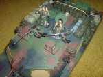
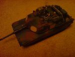
Fwor! Nice. and BIG.
I'm 1/35.
I've got three of these; YGE Bidirectional ESC (8A) 1.2g. I fried one and had to tell from the burt remains what chip it was so I could replace it. This allowed me to learn a lot. It turned out that each one uses 2 N-channel and 2 P-channel FET's on one side and a hustle of microcontrollers, what I assume is a dedicated servo to microcontroller chip, and some capacitors.
That gyro sound really good, can anyone advise what one to get?
It would be hard though as the mathematics would depend on the distance from the target.
Do you think it would be possible to have the turret sence which direction the turret is turning and counter that?
Mine is mainly normal RC kit at the moment. It has tiny LED's from an iPod screen to use as lights and a laser in the turret.
No way I could use smoke of any kind but it sounds good. I got a train with a small oil evaporator. It tells you too use diluted stuff, but my Dad found 3-in-1 oil give huge puffs of grey/black smoke.
I'm 1/35.
I've got three of these; YGE Bidirectional ESC (8A) 1.2g. I fried one and had to tell from the burt remains what chip it was so I could replace it. This allowed me to learn a lot. It turned out that each one uses 2 N-channel and 2 P-channel FET's on one side and a hustle of microcontrollers, what I assume is a dedicated servo to microcontroller chip, and some capacitors.
That gyro sound really good, can anyone advise what one to get?
It would be hard though as the mathematics would depend on the distance from the target.
Do you think it would be possible to have the turret sence which direction the turret is turning and counter that?
Mine is mainly normal RC kit at the moment. It has tiny LED's from an iPod screen to use as lights and a laser in the turret.
No way I could use smoke of any kind but it sounds good. I got a train with a small oil evaporator. It tells you too use diluted stuff, but my Dad found 3-in-1 oil give huge puffs of grey/black smoke
.Attachments
-
 707.2 KB Views: 12
 -
 785.8 KB Views: 12
BeanieBots
Moderator
Thanks for the info Rusty. Maybe a bit too big for my app
I'll check the links and see what's possible. I'm trying to make a realistic gun fire. At the moment I'm using an aerosol smoke cannister controlled with a mini electric valve but it smells worse than the oil units.
As for ESCs, to be quite honest, you can't beat the ready made ones on either performance or cost. More ofetn than not I use ones designed for aircraft with a relay for reverse.
Alband, if you want auto turret levelling then a heli gyro will do the job nicely. Not cheap though. The gyro must be mounted on the barrel or at least such that it moves with it. Position demand goes into gyro, servo plugs into gyro. Set gain to highest you can that does not cause oscillating, job done. It will always stay at the angle you set.
Rickharris
Senior Member
Just so happens I have a heli Gyro I don't want - If interested get in tough PM
I don't think a gyro will do, (me and Rick have PM'ed and it just wont work ) but what about an accelerometer like this?
http://www.sparkfun.com/commerce/product_info.php?products_id=853
Analogue output I think, solder-able, very small and cheep.
What about turret rotation; that would be impressive and easier to calculate if the correct sensor could be found. Acceleration would be to had I think but what about this...
Use that same sensor above,
have it mounted on the axis and able to turn on it but not quite level,
this would give a reading on each axis of slightly something,
the direction relative to the hull could be determined by the amount and direction of each axis.
) but what about an accelerometer like this?http://www.sparkfun.com/commerce/product_info.php?products_id=853
Analogue output I think, solder-able, very small and cheep.
What about turret rotation; that would be impressive and easier to calculate if the correct sensor could be found. Acceleration would be to had I think but what about this...
Use that same sensor above,
have it mounted on the axis and able to turn on it but not quite level,
this would give a reading on each axis of slightly something,
the direction relative to the hull could be determined by the amount and direction of each axis.
BeanieBots
Moderator
Don't know why you think a gyro won't work. They do for me. Even does all the hard work of PID pulse manipulation for you.
Anyway, yes, an accelerometer will work. It's what's used in the gyros but it will be up to you to do the signal conditioning and that includes a PID loop if you want rock steady postion holding as apposed to "not moving about quite as much as without one".
Anyway, yes, an accelerometer will work. It's what's used in the gyros but it will be up to you to do the signal conditioning and that includes a PID loop if you want rock steady postion holding as apposed to "not moving about quite as much as without one".
Gyro's are standardly very big and expensive if you get one that is small.
I've reconsidered by idea about turret rotation and realised it wont work as it is relative to the hull, no t the world. It would need to be relative to the world so the only solution I can think of is a compass IC. I have no experiance of these, anyone? - How acurate, effected by magnets e.g. motors?
PID pulse?
I don't know what PID is but since you refer to #72 I'm guessing it's "Position demand"? - I though it was some sort of protocol or way of editing a signal.
I understand how it would work and I think it would work well, it's just too big and as mentioned, expensive.
I found these:
http://www.active-robots.com/products/sensors/sparkfun/8658.shtml I don't need three axis, only 1 but this is the cheapest.
http://www.active-robots.com/products/sensors/sparkfun/hmc6352.shtml
both i2c compatible and could both be controlled with an 18X.
The 18X could take commands from the hull, turn them into servo commands then edits the servo commands according to the accelerometer.
If I had that compass in the turret though, I would need to send the info down into the hull so that the turret rotation signals can be edited. Could I use the same serial line to send this down?
InvaderZim
Senior Member
Re: gyros.
If they're too big (at reasonable cost) to put in the turret, you can always put it in the body. That would allow your body to know its orientation, and turn the turret to compensate (so that it appears as if the turret stays "locked on" to a target even as the tank drives around).
It should work about as well as having the sensor in the turret: once you "zero" the system, the tank will work to keep the turret pointed at the same rotation and inclination that it started with, regardless of how the wheels move or how the body tilts. And of course allow you to manually move the turret, and then re-set the "target."
The disadvantage is the math might be a bit harder to translate the body orientation into a turret orientation; having the sensor on the barrel itself simplifies the math I'd think. You'd have to put something together and see if the performance is acceptable.
Hope that made sense!
InvaderZim
Senior Member
Re: PID loop
It's a means of changing a variable to maintain a setpoint, like controlling a heater to maintain temperature. It's "smarter" than just kicking it on and off, because it allows you to "anticipate" what will happen, like turning the heat on just *before* it gets too cold. Check wikipedia!
It's a means of changing a variable to maintain a setpoint, like controlling a heater to maintain temperature. It's "smarter" than just kicking it on and off, because it allows you to "anticipate" what will happen, like turning the heat on just *before* it gets too cold. Check wikipedia!